Greenhouse rainwater harvesting: a setup plan for Bekaa farms
A greenhouse roof is already a large water-collection surface. Without a harvesting system, rainfall runs through gutters, across compacted ground, and away from the irrigation network.
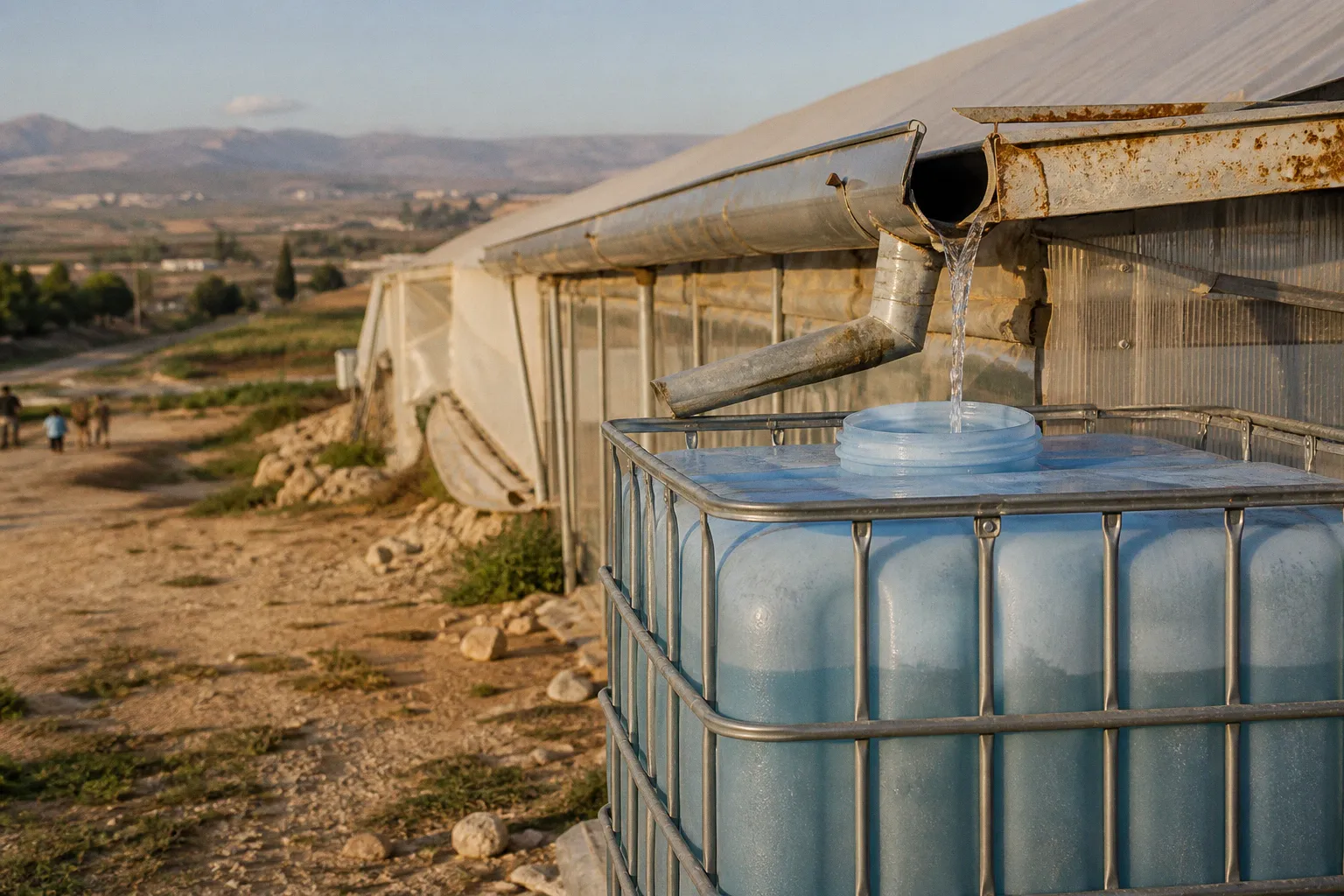
With correctly sized conveyance, filtration, storage, and pumping, the same roof becomes a measurable water asset.
For a Lebanese cooperative, the engineering question is not whether greenhouse rainwater harvesting is technically possible. It is whether the system can capture enough water, at the right time and quality, to justify the capital expenditure. The answer depends on four baseline metrics: roof area, rainfall depth, runoff efficiency, and crop irrigation demand.
The calculation begins with a simple relationship:
Harvested water in litres = catchment area in square metres × rainfall in millimetres × runoff coefficient
One millimetre of rain falling on one square metre of roof produces approximately one litre before losses. A smooth plastic, glass, or sheet-metal roof normally uses a runoff coefficient between 0.80 and 0.95, reflecting evaporation, splashing, leakage, filter losses, and the water diverted during the first flush.
That makes the greenhouse roof more useful than an open collection basin. Its surface is already elevated, defined, and connected to an existing structure. The remaining task is to prevent contamination and move the captured water into storage without creating a second set of maintenance problems.
Calculating your catchment potential: the 1 mm-to-1 L rule
The first phase should be a measurement exercise, not an equipment purchase. Record the external greenhouse dimensions, excluding walkways and adjacent ground. For a simple rectangular structure, the horizontal catchment area is:
Length × width = catchment area
The roof slope does not materially change this basic calculation when the horizontal footprint is used. A steep roof has a larger physical surface area, but rainfall is measured as a vertical depth over a horizontal area. The engineering model therefore starts with the greenhouse footprint rather than the total length of the sloping roof sheets.
Consider a greenhouse with a catchment area of 1,000 m². A rainfall event of 20 mm produces a theoretical volume of:
1,000 m² × 20 mm = 20,000 litres
Applying a runoff coefficient of 0.90 reduces the recoverable volume to approximately:
20,000 × 0.90 = 18,000 litres
This figure still excludes the initial dirty runoff that should be diverted away from the tank. If the system rejects a further portion during the first flush, the usable volume will be lower. The calculation is nevertheless sufficient for a preliminary design.
For a cooperative operating several greenhouse blocks, calculate each block separately before combining the totals. Different roof materials, elevations, gutter conditions, and pipe routes can produce different collection efficiencies. A single aggregate figure can conceal an underperforming block.
| Parameter | Example value | Engineering effect |
|---|---|---|
| Greenhouse footprint | 1,000 m² | Defines the basic catchment area |
| Rainfall event | 20 mm | Provides the gross water volume |
| Theoretical yield | 20,000 L | One litre per square metre per millimetre |
| Runoff coefficient | 0.90 | Allows for collection losses |
| Estimated captured volume | 18,000 L | Preliminary storage and pumping input |
| First-flush diversion | Site-specific | Reduces usable volume but improves water quality |
The example is not a rainfall forecast for the Bekaa Valley. It is a sizing calculation. Before final tank procurement, the cooperative should use localized rainfall records for the specific farm or valley, preferably with monthly rather than annual totals. Annual rainfall can make a system appear adequately supplied while concealing a mismatch between the wet season and the crop’s irrigation schedule.
That timing problem is central. A tank sized only from annual water volume may be too small during intense rainfall or too large relative to actual irrigation demand. The correct design compares monthly inflow with monthly crop consumption and identifies the storage deficit between collection periods.
A roof does not create water security by itself. It creates a predictable inflow; storage determines whether that inflow remains useful after the weather changes.
Establishing the farm baseline
Before moving to gutters, document the demand side of the system. The following measurements create a defensible baseline:
- Total greenhouse area connected to the proposed collection network.
- Crop area, crop type, and planting schedule.
- Existing irrigation method, including drip-line flow rate and operating pressure.
- Daily or weekly irrigation volume during the highest-demand period.
- Available electrical supply or solar generation for pumping.
- Existing tanks, reservoirs, filters, and distribution lines.
- Roof material, age, repairs, and areas where dust or chemical residues accumulate.
- Elevation differences between greenhouse blocks, tanks, and irrigation zones.
The baseline should be recorded in litres and cubic metres, not only in pump operating hours. A pump runtime is useful only when its actual flow rate has been measured. A nominal pump rating does not describe the delivered volume after pipe friction, elevation gain, filters, valves, and pressure regulation.
Selecting materials for maximum runoff efficiency
The collection surface is the first component that determines system performance. Smooth plastic, glass, and sheet metal generally produce runoff coefficients in the 0.80–0.95 range. The upper end is possible only when the roof and conveyance network are clean, intact, and properly sloped toward the gutters.
Greenhouse plastic is often effective as a catchment surface, but its performance depends on installation quality. Sagging sections can hold sediment and organic matter, while patched or heavily weathered film can shed fragments into the gutter. A collection system should not be attached to a roof that is already failing structurally or shedding material into the irrigation supply.
Gutters should be selected for the expected peak flow rather than the average seasonal volume. A narrow gutter may transport the annual total adequately while overflowing during a short, high-intensity storm. Overflow at the greenhouse edge can erode soil, undermine foundations, and return contaminated water to the collection route.
The practical material sequence is straightforward:
1. Roof catchment: Use the existing greenhouse covering where it is structurally sound and chemically suitable for water collection.
2. Gutters: Install continuous gutters with a controlled slope toward downspouts. Avoid low points where sediment and standing water can accumulate.
3. Downspouts: Place them according to roof length and expected flow. Long uninterrupted gutter runs increase the hydraulic load at the downstream end.
4. Debris screens: Use removable screens at gutter inlets and downspout entries. Screens must be accessible from ground level or through a safe maintenance route.
5. First-flush diverter: Route the first portion of each rainfall event away from the storage tank.
6. Storage tank: Use an above-ground or underground tank with a sealed inlet, screened ventilation, overflow protection, and a drain or cleanout point.
7. Pump and distribution line: Deliver filtered water to the irrigation system at the required flow and pressure.
The coefficient should be treated as a design variable rather than a universal constant. A new, smooth roof with efficient gutters may justify a coefficient closer to 0.95. A dusty roof with degraded film, splash losses, and frequent first-flush diversion should be modelled closer to 0.80.
This difference is not academic. On a 1,000 m² roof receiving 20 mm of rain, a coefficient of 0.95 produces an estimated 19,000 litres, while a coefficient of 0.80 produces 16,000 litres. The gap is 3,000 litres from one rainfall event. Across repeated events, an optimistic coefficient can distort the storage and irrigation plan.
Above-ground or underground storage
Above-ground tanks are easier to inspect, clean, modify, and connect to new pipework. They also expose the water to higher temperature variation and occupy valuable farm space. Their support base must be level and capable of carrying the full operating load. Water weighs approximately one tonne per cubic metre, so a 20 m³ tank represents roughly 20 tonnes of stored water before the tank, fittings, and support structure are included.
Underground tanks preserve surface area and reduce exposure to temperature variation. They require excavation, structural assessment, access covers, waterproofing, and more complex repair procedures. The installation location must also leave adequate clearance for excavation, pipe connections, cleaning, and future pump maintenance.
For a cooperative, the correct choice is usually determined by land value, construction access, groundwater conditions, and the likelihood of expanding the collection network. A cheap tank in a poor location can create more operating cost than a larger tank installed with accessible pipe routes and safe maintenance access.
Engineering the filtration and first-flush diversion
The first rainfall after a dry period is not equivalent to clean irrigation water. It can carry dust, bird droppings, plant debris, fragments of greenhouse material, and residues deposited on the roof between rainfall events. Sending this volume directly into the tank increases sediment accumulation and transfers contamination into the irrigation network.
A complete greenhouse roof water harvesting setup should therefore separate three functions:
- Coarse debris removal at the roof and gutter.
- First-flush diversion for the initial contaminated runoff.
- Fine filtration before the water enters drip irrigation equipment.
These functions should not be combined into one small filter. A screen that stops leaves is not designed to remove fine particles, and a fine irrigation filter can become a high-maintenance substitute for a missing first-flush device.
The first-flush unit
A first-flush diverter temporarily stores or redirects the initial runoff volume. Once the diverter fills, a float, valve, restriction, or controlled overflow allows the cleaner subsequent flow to enter the main storage tank. The diverted water should discharge to a stable drainage location where it will not erode the greenhouse foundation or return to the tank inlet.
The required diversion volume depends on roof dust load, surrounding conditions, and the cooperative’s water-quality standard. It should be established through inspection and maintenance records rather than selected as an arbitrary tank accessory.
The diverter must also reset reliably after each event. A device that remains full after one storm can reject the clean runoff from the next storm. A device that drains too quickly may send contaminated water into storage before the roof has been adequately rinsed.
Filtration before drip irrigation
Drip emitters operate through small passages that are vulnerable to sediment. Rainwater captured from a greenhouse roof should not be applied directly to drip lines without filtration. Even visually clear water may contain fine particles that accumulate in emitters and pressure-compensating components.
The filtration train should include:
- A coarse inlet screen that can be removed without dismantling the pipe network.
- A settling zone or tank geometry that prevents the pump from drawing directly from the sediment layer.
- A serviceable irrigation filter sized for the pump flow rate.
- Pressure gauges before and after the filter to show when the filter is loading with sediment.
- A flushing connection or backwash arrangement where the selected filter allows it.
- Isolation valves so the filter can be cleaned without draining the complete storage tank.
The filter should be selected from the actual irrigation flow, not from the tank volume. A large tank can feed a small drip zone or several zones operating simultaneously. The filter must accommodate the highest expected flow while maintaining the pressure required at the most distant emitters.
Water quality should also be evaluated against the crop and the irrigation equipment. Harvested rainwater is often relatively low in dissolved minerals, but roof contamination and storage conditions can change its suitability. If the cooperative uses fertilizers through fertigation, the compatibility of the harvested water with the dosing equipment should be confirmed through the existing irrigation protocol rather than assumed from appearance.
Sizing storage tanks for Bekaa Valley irrigation needs
Storage is the most expensive component in many rainwater harvesting systems because it must hold water between collection events. The tank should be sized against both supply and demand.
A preliminary agricultural guideline places covered storage requirements at approximately 100–200 m³ per 1,000 m² of greenhouse catchment area, depending on local crop irrigation needs and rainfall distribution. This is a planning range, not a universal specification. A farm with low water demand and frequent rainfall may need less storage. A farm with high-demand crops and long dry intervals may require more, although the additional volume may not be economically justified if the roof cannot refill it.
For a 1,000 m² greenhouse, the guideline corresponds to a tank capacity in the range of 100–200 m³. At the lower end, the tank holds 100,000 litres; at the upper end, it holds 200,000 litres. The physical and financial consequences are substantial, particularly for underground construction.
A better sizing process uses a water-balance model:
1. Estimate monthly rainfall for the specific farm location.
2. Multiply each month’s rainfall by the connected catchment area.
3. Apply the runoff coefficient.
4. Subtract first-flush and conveyance losses.
5. Subtract monthly irrigation demand.
6. Carry the remaining storage balance into the next month.
7. Identify the lowest storage point and the months when the tank reaches overflow or depletion.
8. Test alternative tank capacities against the same sequence.
The model should include an initial storage condition. A tank entering the wet season at 10% capacity produces a different result from a tank entering at 60%. This distinction matters when the greenhouse is already drawing from stored water before the next major collection period.
Avoiding oversized storage
Oversizing is not a harmless error. A tank that rarely fills ties up capital, occupies land, and may create water-quality problems through long residence times. Large volumes also increase structural requirements, foundation costs, access requirements, and the consequences of leakage.
Undersizing produces a different failure pattern: the tank fills during rainfall, overflow bypasses the irrigation system, and the farm still faces a shortage later. The visible result is a full tank during the wet period and an empty tank when crops require water. That is a storage timing failure, not evidence that rainwater harvesting is ineffective.
The economically rational tank is the smallest capacity that captures the useful portion of available runoff while meeting the cooperative’s defined irrigation target under the selected rainfall scenarios. If the water balance shows that the tank will remain empty for extended periods, expanding storage will not correct the problem. The limiting factor may be catchment area, rainfall timing, irrigation demand, or a leaking distribution network.
Tank volume is not water security. The relevant metric is the percentage of irrigation demand supplied from stored water after collection, filtration, and pumping losses.
Strategic tank placement and distribution infrastructure
Tank placement determines the length, cost, and reliability of the pipe network. For an underground tank, positioning it approximately 2–10 metres from the greenhouse structure generally balances short pipe runs against operational interference. The exact location should be selected after mapping gutter outlets, vehicle routes, electrical access, drainage, and future greenhouse expansion.
The tank should not sit where overflow can wash toward the greenhouse foundation. The overflow route needs a visible, protected discharge point. A hidden overflow is a fault that remains undetected until the tank is already failing to store water.
The distribution system should be divided into functional sections:
- Collection lines from gutters to the tank.
- Tank inlet and overflow.
- Pump suction line with appropriate intake protection.
- Main filtered irrigation line.
- Valves for individual greenhouse blocks.
- Pressure regulation and monitoring.
- Drain and flush points at low sections of pipework.
Pump selection should follow a hydraulic calculation. The required pump duty is defined by flow rate and total dynamic head, which includes elevation, pipe friction, valves, filters, and the pressure required by the irrigation system. A pump rated only by maximum flow may deliver inadequate pressure once connected to a long pipe run and a loaded filter.
For farms using solar-powered irrigation, the pumping schedule should be matched to both water demand and available generation. The system may use direct daytime pumping into an elevated tank, battery-supported operation, or a hybrid arrangement with grid or generator backup. The choice affects capital expenditure and operating resilience. It should be evaluated through delivered cubic metres per kilowatt-hour rather than panel capacity alone.
Commissioning sequence
A staged installation reduces the risk of discovering basic design errors after the tank is full.
Phase 1: Survey and baseline
Measure the greenhouse footprints, inspect roof materials, map downspout routes, record existing irrigation demand, and identify the final tank location. Confirm that the structure can receive gutters without compromising the roof covering.
Phase 2: Collection network
Install gutters, downspouts, screens, and inspection points. Test the network with controlled water before connecting it to the storage tank. The test should reveal low points, leaks, overflow paths, and sections where water bypasses the gutter.
Phase 3: Water-quality controls
Install the first-flush diverter and confirm that it resets after drainage. Add the tank inlet screen, sediment control, and irrigation filter. Pressure gauges should be installed where maintenance staff can read them without entering a confined or hazardous area.
Phase 4: Storage and pumping
Commission the tank overflow, drain, pump suction, isolation valves, and distribution line. Measure actual pump flow at the irrigation manifold. Compare the measured value with the design assumption and update the operating schedule accordingly.
Phase 5: Performance monitoring
Track rainfall, tank level, irrigation volume, filter pressure differential, overflow events, and pump runtime. These are the baseline metrics that determine whether the system is producing useful water or merely moving it between components.
Maintenance should be scheduled around these measurements:
- Clear gutter screens after dusty periods and before forecast rainfall.
- Inspect the first-flush diverter for sediment and failed reset mechanisms.
- Clean the tank inlet and remove accumulated sediment at defined intervals.
- Record filter pressure before and after cleaning.
- Check tank covers, vents, overflow pipes, and access seals.
- Inspect pipe joints and valves for leaks.
- Verify pump output at least whenever the irrigation configuration changes.
The operating team should also keep the harvested-water network physically separated from any source that could backflow into the tank. Cross-connections create a contamination pathway and can make the water balance appear correct while undermining the purpose of the system.
The investment decision
The greenhouse rainwater harvesting system in Lebanon should be approved on measured water displacement, not on the gross volume falling on the roof. The useful output is the quantity that survives runoff losses, first-flush diversion, filtration, storage, pumping, and irrigation application.
A cooperative can calculate the techno-economic case with five numbers:
1. Annual and seasonal litres captured.
2. Litres delivered to the irrigation manifold.
3. Percentage of irrigation demand supplied by harvested water.
4. Capital expenditure for gutters, filters, tanks, pumps, controls, and civil works.
5. Annual maintenance and replacement cost.
The resulting return-on-investment model should compare the harvesting system with the cooperative’s existing water source, including pumping energy, transport, treatment, storage, and reliability constraints. Exact equipment pricing in Lebanon varies by supplier, import conditions, currency, and civil-work requirements, so a fixed national cost estimate would have limited analytical value without a site-specific bill of quantities.
The strongest projects will normally have three characteristics: substantial connected roof area, a clear irrigation demand during the storage drawdown period, and an existing distribution network that can accept filtered water without complete reconstruction. The weakest projects will have small catchments, low crop demand, poor roof condition, or tanks installed without a water-balance model.
For Bekaa farms, the engineering verdict is therefore conditional but precise. The roof catchment potential can be calculated immediately using the 1 mm-to-1 litre rule and a defensible runoff coefficient. The collection hardware is straightforward: gutters, screens, first-flush diversion, covered storage, filtration, and a correctly specified pump. The capital decision becomes sound only when monthly inflow and irrigation demand are compared rather than annual rainfall totals being treated as supply.
A well-designed system converts an exposed greenhouse surface into controlled irrigation inventory. A poorly designed one converts rainfall into sediment, overflow, blocked emitters, and an oversized tank. The difference is not the technology. It is the quality of the baseline measurements and the discipline of the water-balance calculation.