Gravity drip irrigation: a step-by-step terrace project
On terraced farms, water rarely fails because there is not enough of it in the tank. More often, it fails because the system asks water to behave the same way at every level of the slope.
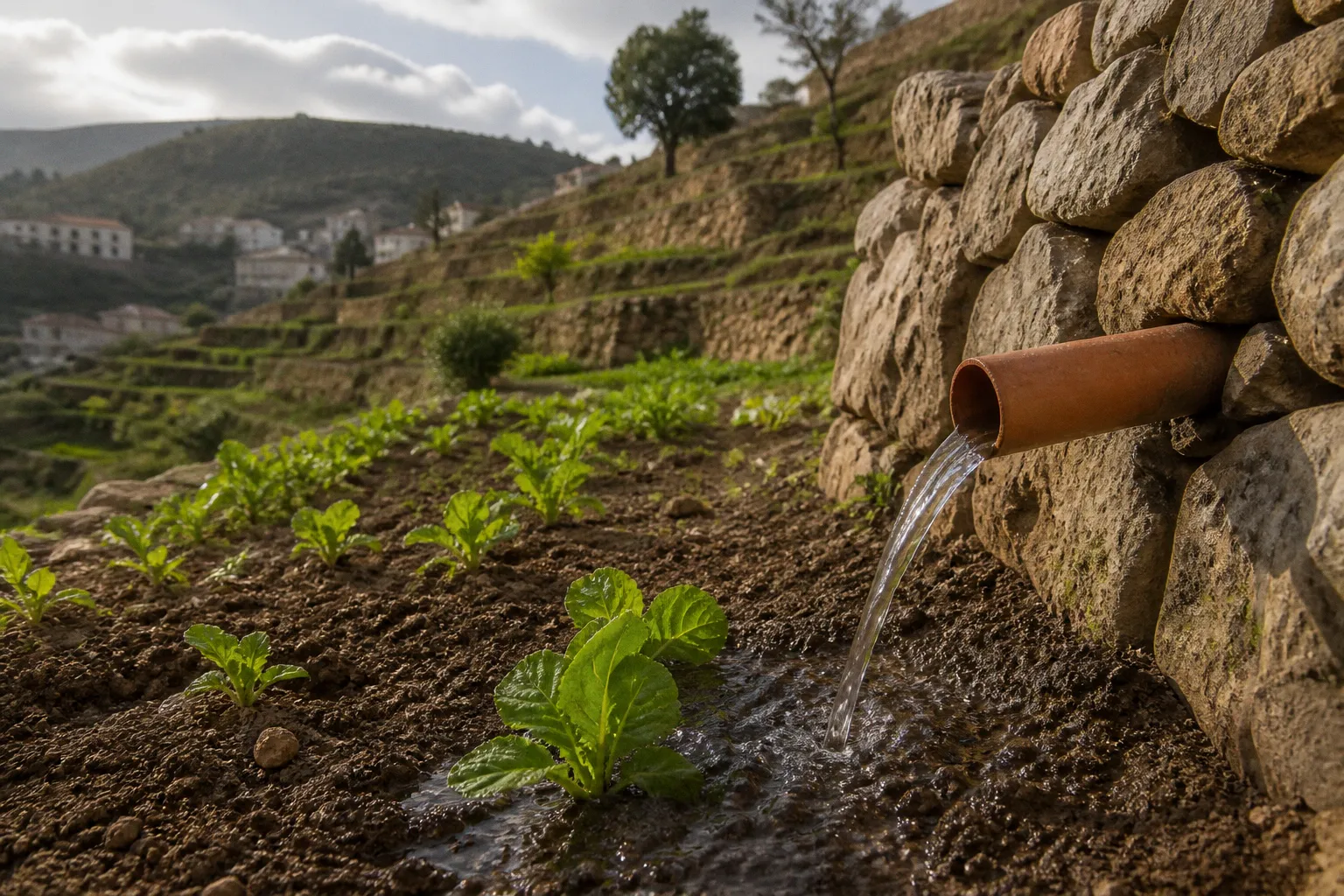
The first terrace receives a crisp, reliable flow; the lowest line receives too much pressure; another lateral opens weakly; and by the end of the irrigation cycle, some plants are standing in wet soil while others are waiting for moisture.
A well-planned gravity fed drip irrigation system design turns elevation into working pressure, but it does not treat gravity as a substitute for engineering. We still need to calculate hydraulic head, account for friction losses, filter the water carefully, and arrange pipes so the terraces share water rather than compete for it. On Lebanese hillsides, where plots may be narrow, stepped, and separated by stone retaining walls, the layout is often more important than the size of the tank.
The good news is that a terrace irrigation system can remain relatively simple. A raised reservoir, a properly sized mainline, low-pressure emitters, a dependable filter, and a few control points can take us a long way. The system succeeds when each part is designed as a member of the same collective effort.
Start with the elevation, not the pipe
The first measurement in a gravity drip project is the vertical distance between the water surface in the reservoir and the highest irrigation point. This distance is called hydraulic head. It is the source of the pressure that moves water through the network.
The basic relationship is:
- Every 2.31 feet of elevation creates approximately 1 psi of pressure.
- One foot of elevation creates about 0.433 psi.
- One metre of elevation creates roughly 0.1 bar.
That means a tank raised 3 metres above the highest irrigation level provides approximately 0.3 bar of pressure before we subtract losses from the filter, valves, fittings, pipe length, and elevation changes across the terraces.
This 3-metre figure is a useful practical baseline for basic low-pressure emitters. A smaller height may still move water through an open line, but it may not provide enough pressure to open or operate ordinary drip emitters consistently. A tank only 2 or 3 feet above the first lateral is not a gravity irrigation system in the reliable sense; it is a container draining through a pipe, with very little pressure available to overcome resistance.
Mapping the terrace before choosing the tank
We do not need a surveyor's instrument for the first planning pass, but we do need more than an estimate made from the wall below the house. Measure or approximate:
- The elevation of the reservoir water surface when the tank is full.
- The elevation of the highest lateral and the lowest lateral.
- The length of each terrace from the planned mainline to its far end.
- The direction of the slope on every step.
- The location of access paths, retaining walls, gates, and machinery routes.
- The position of the water source and the place where filtration can be serviced.
The important reference is the water level, not the base of the tank. A 7-foot-tall tank can produce a pressure difference of up to about 3 psi between its full and nearly empty states. That is a substantial change in a low-pressure system, where the total operating range may be only 0.3 to 1 bar.
For this reason, we should calculate the system at two conditions:
1. The tank is full: maximum available head and greater pressure at the lower terraces.
2. The tank is near its minimum operating level: reduced pressure and weaker flow at the upper terraces.
If the system only works while the reservoir is full, the design is not finished. Our growers need a network that remains useful through the irrigation cycle, not one that performs beautifully for the first few minutes.
In gravity irrigation, elevation is our pump—but only if we measure it honestly and distribute its pressure carefully.
A simple head calculation
Suppose the water surface in the tank is 4 metres above the highest irrigation level. The theoretical pressure at that point is approximately 0.4 bar. If the lowest terrace is another 8 metres downhill, the total elevation difference becomes 12 metres, and the pressure at that lower point could reach approximately 1.2 bar before friction and fittings are considered.
That difference is the central challenge. The upper terrace may struggle with limited pressure, while the lower terrace may receive more flow than its emitters can handle. A system designed only around the tank height may therefore overwater the bottom and under-irrigate the top.
The solution is not necessarily a larger tank or a taller tower. It is a layout that follows the terraces, divides the pressure sensibly, and uses components made for low-pressure operation.
Lay the mainline across the terraces
On sloped ground, pipe direction determines how much pressure variation the network experiences. A common mistake is to run one long mainline straight downhill and connect every terrace to it. This is easy to install, but it allows elevation pressure to accumulate toward the bottom.
For terraced land, the mainline should generally follow the contours of the terraces, running across or along the steps rather than directly down the fall of the hillside. The sub-mains then branch from that contour mainline and serve individual terrace levels.
This arrangement gives us several benefits:
- Each terrace can be isolated and irrigated independently.
- The mainline experiences less sudden elevation change.
- Pipe lengths become easier to inspect and flush.
- Pressure can be reduced or adjusted at each step.
- A damaged lateral does not drain the entire hillside.
- We can adapt watering times to different crops and soil depths.
The exact arrangement depends on the shape of the land. A narrow terrace with one crop may need only one lateral line. A wider terrace may need several laterals connected to a short sub-main. What matters is that the distribution network follows the physical structure of the farm instead of forcing the farm into a convenient pipe pattern.
Mainline, sub-main, and lateral dimensions
For a small-farm low-pressure network, a practical starting point is often:
| Network component | Common size or rating | Purpose in the terrace system |
|---|---|---|
| Mainline header | 20–25 mm PVC or polyethylene | Carries water from the filter and distributes it along the terrace contours |
| Sub-main | Sized according to terrace length and flow demand | Feeds one terrace or a defined group of laterals |
| Lateral tubing | 16 mm | Carries water alongside crop rows |
| Inline emitters | 2.0–4.0 L/h | Delivers measured flow to the root zone |
| Filter | At least 120–150 mesh | Removes particles that can clog emitters |
These are not universal prescriptions. A long terrace with many rows may need a larger sub-main, while a small orchard block may work with a simpler arrangement. Pipe diameter affects friction loss, and friction loss matters much more when our available pressure is measured in tenths of a bar rather than several bars.
A mainline that is too narrow may appear adequate when only one terrace is open. Once several sections run together, the farthest rows begin to lose flow. We should therefore decide whether the system will irrigate:
- One terrace at a time;
- Several terraces in separate zones; or
- The entire plot simultaneously.
For gravity-fed irrigation, zoning is often the friendlier solution. Opening fewer terraces at once reduces the total flow demand and gives each zone more stable pressure. It also makes it easier to match irrigation time to soil and crop needs.
Run sub-mains down the slope with control
Although the mainline should generally follow the contour, sub-mains may need to run downhill to serve the laterals. This is where pressure management becomes essential.
As water moves down the slope, every increase in elevation difference adds pressure. On a steep sub-main, the lower end can receive significantly more pressure than the upper end. If the sub-main slope exceeds roughly 10% to 15%, emission uniformity can deteriorate sharply without pressure controls.
We can respond in several ways:
1. Use pressure-reducing valves at terrace transitions. These limit the pressure entering a lower section and protect the laterals below.
2. Divide the downhill run into shorter sections. Instead of one continuous sub-main, use separate terrace branches with their own valves.
3. Change pipe sizes gradually. Stepped pipe sizing can help manage pressure and flow, although it must be planned rather than improvised.
4. Place flush points at low locations. Sediment naturally travels downhill. A flush valve or removable end cap at the lowest point makes cleaning possible.
5. Avoid connecting all lower terraces to one uncontrolled vertical pipe. The resulting pressure difference may be too large for low-pressure emitters.
A good terrace system is not one in which every valve is permanently open. It is one in which we can control the order, duration, and pressure of irrigation without climbing the hillside with a wrench each time.
Choose emitters that can work with low pressure
Not every drip emitter is suitable for gravity-fed irrigation. Many pressure-compensating emitters are designed for pump or municipal networks operating at much higher pressures, often around 15–30 psi. They may not open correctly when the available gravity head is only a few psi.
This is a critical distinction. A pressure-compensating emitter can be excellent in a pressurized system and completely unsuitable in an unboosted gravity network. We should select emitters specifically rated for low-pressure use, then match their discharge to the crop and soil.
Typical low-pressure drip systems use emitters in the range of 2.0 to 4.0 litres per hour. The lower end may be more manageable on a weak-pressure upper terrace or in heavy soil. Higher-flow emitters can be useful where the pressure is reliable and the soil can absorb water without creating runoff.
Keep the crop row and the emitter together
Emitter selection is only half of the decision. Placement determines whether the water reaches the root zone evenly.
For annual vegetables, laterals are usually placed along the planting rows, with emitter spacing selected according to crop spacing, soil texture, and the width of the wetted zone. On a terrace with shallow soil over stone, water may move sideways more than it moves downward. On a deep, finer soil, a wider emitter spacing may still create a connected moisture band.
For orchards, one emitter may not be enough as trees mature. Young trees can be served by a small number of emitters near the root zone, but the wetting pattern should expand as the canopy and roots expand. It is better to add a second lateral or additional emitters than to run one line at an excessive flow rate.
We should also resist the temptation to make every terrace identical. A crisp lettuce row, a young citrus block, and established olive trees do not have the same water demand. The infrastructure can be shared while the watering schedule remains crop-specific.
Filtration is not optional
Gravity-fed irrigation still needs filtration. In fact, low-pressure emitters can be especially vulnerable because there is less pressure available to push particles through a partially blocked passage.
Spring water and storage tanks may carry fine limestone material, organic debris, algae, or sediment from an unlined collection point. Even when the water looks clear in a bucket, small particles can accumulate inside emitters over time.
A fine physical mesh or disc filter of at least 120–150 mesh is necessary for a drip network. The filter should be installed before the mainline branches into the terraces, where it can protect the entire system. It also needs to be accessible: a filter hidden behind a wall is a future maintenance problem.
The filtration assembly should include:
- An isolation valve before the filter.
- A drain or flush point.
- A filter body that can be opened without dismantling the pipe.
- A pressure gauge where pressure readings are useful.
- A second isolation valve after the filter if the layout allows it.
The filter must be cleaned before the pressure loss becomes severe. In a pump system, a dirty filter may show up as a pressure drop that is inconvenient but obvious. In a gravity system, the same blockage can make the upper terraces stop irrigating altogether.
A simple maintenance rhythm is more valuable than a complicated promise of "low maintenance." During the irrigation season, inspect the filter frequently at first, then adjust the cleaning interval according to the amount of sediment found. Flush the mainline and sub-mains at their ends, especially after repairs or periods when the water source has carried silt.
A gravity network can forgive modest pipe sizes; it cannot forgive a neglected filter.
Build the reservoir as part of the irrigation system
The reservoir is not merely a water container placed above the field. Its height, outlet position, refill pattern, and internal cleanliness all affect irrigation performance.
The outlet should be positioned so that sediment at the bottom of the tank is not pulled directly into the filter. A settling area or drain at the lowest point can help us remove accumulated material. The tank should also be covered or protected from debris and excessive sunlight where practical, because leaves, insects, and algae can all become filtration problems.
The usable water level deserves special attention. If the outlet is too close to the bottom, the system may lose effective head before the tank is empty. If the tank is tall, pressure will vary as the water level falls. We should set a minimum operating level and design the irrigation schedule around the pressure available at that point.
Managing the full-to-empty pressure range
A tank with a 7-foot water-height difference can create up to about 3 psi of pressure variation between full and nearly empty. In a conventional pressurized network, that might be a minor adjustment. In a gravity system, it can change emitter discharge noticeably.
Several design choices can reduce the effect:
- Irrigate the most pressure-sensitive upper terraces while the tank still has sufficient water head.
- Use separate zones rather than opening the entire system at once.
- Keep the highest laterals relatively short.
- Use low-pressure emitters with a known operating range.
- Place valves where we can balance terrace flow.
- Avoid relying on pressure-compensating emitters designed for high-pressure systems.
- Maintain a consistent refill schedule where the water source allows it.
If the tank is replenished during irrigation, the inflow should not disturb sediment or send unfiltered water directly into the outlet. A calm inlet arrangement, simple settling space, and an overflow path can protect the clarity of the stored water.
For some farms, a single elevated tank may not provide enough usable head across a large vertical spread. In that case, smaller intermediate tanks or separate zones may be more effective than building one very tall structure. The right answer depends on the land, available materials, safety constraints, and the cost of supporting the reservoir securely.
Use the terrace contours to protect uniformity
Uniformity is the measure that tells us whether the network is truly serving the crop. A system may look tidy and still deliver very different quantities of water from one end to another.
Field testing on hilly terraces has shown that emission uniformity can reach up to 91.03% at a 3.0-metre hydraulic head on flat ground. That performance can degrade significantly when sub-main slopes become steep without pressure control. The lesson is not that terraces prevent good irrigation; it is that the same network that performs well on level ground can lose its advantage the moment slope is introduced and ignored.
Practical ways to defend uniformity across the slope:
- Match lateral length to pressure. Shorter laterals on lower terraces reduce friction variation; longer laterals can sit on flatter upper sections.
- Stagger irrigation cycles. Run the upper terraces first, when the tank is fullest, and shift to the middle and lower zones as the level drops.
- Use the same emitter model throughout a zone. Mixing 2 L/h and 4 L/h emitters on one lateral complicates troubleshooting and produces uneven bands.
- Close off the ends of unused laterals. Open-ended drip tubing invites rodents, sun damage, and pressure loss.
- Walk the line while it runs. A short field check after installation catches more problems than any spreadsheet.
A short field test worth doing
A practical uniformity check does not require laboratory instruments. Run the zone at its normal operating pressure, place identical catch containers under four emitters spaced along the lateral (near the inlet, one-quarter of the way down, three-quarters down, and at the far end), and let them collect for the same time. Compare the volumes. If the lowest emitter delivers less than about 85% of the highest emitter, the lateral is too long for the available pressure, the pipe is partially blocked, or the emitter model is mismatched to the head.
Repeat the same test on a different terrace. When the numbers tell a consistent story across the farm, the design is doing its job. When they do not, the gap usually points back to slope, friction, or a missing control valve.
Bringing the steps together
A terrace drip system earns its reliability in the small decisions: a tank placed high enough to work, a mainline that follows the contour instead of the fall, a filter that is easy to reach and easy to clean, emitters matched to the head we actually have, and a routine that respects the difference between full and nearly empty.
These pieces do not need to be expensive or elaborate. They need to be honest about the slope. Lebanese terraced farms already do the hard part of shaping the land; the irrigation network simply has to respect that work, distributing the pressure that gravity has already given us rather than fighting it.
When the system is built this way, the upper terrace is not the weak point, and the lower terrace is not the over-watered one. The whole hillside waters together, and the harvest at the bottom looks much the same as the harvest at the top.