Subsurface drip irrigation setup for Lebanese orchards
An estimated 87,000 hectares of irrigated farmland operate across Lebanon. Roughly 45 percent of that total — approximately 39,150 hectares — sits in the Bekaa Valley, a semi-arid basin where…
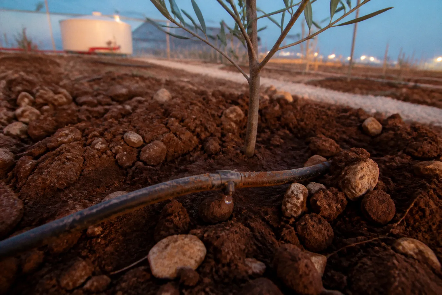
An estimated 87,000 hectares of irrigated farmland operate across Lebanon. Roughly 45 percent of that total — approximately 39,150 hectares — sits in the Bekaa Valley, a semi-arid basin where groundwater tables have been declining for decades under the combined pressure of conventional flood irrigation and expanding cultivation. In a region where surface-applied drip systems already represent the progressive alternative, evaporation and surface runoff still account for substantial fractions of delivered volume. Subsurface drip irrigation (SDI) addresses a large part of those losses by relocating the delivery point below the soil surface and closer to the active root zone. Depending on the baseline system, soil, crop, and management quality, reported water savings can reach 30 to 50 percent without a corresponding yield penalty or quality reduction.
For Lebanese orchard operators dealing with rising input costs, unreliable municipal water schedules, and increasing pressure to make productive use of treated wastewater, SDI is not an emerging curiosity. It is a capital allocation decision with a calculable return — provided the installation is designed for the actual soil, pressure regime, water source, and maintenance capacity of the farm.
The question confronting cooperative members and individual growers is not simply whether SDI works. It is how to specify, install, and maintain a system that performs reliably in Lebanese soil conditions, at Lebanese pressure tolerances, and with the non-conventional water sources now entering the regional supply chain.
The Mechanics of Root-Zone Water Delivery in Semi-Arid Climates
Surface drip irrigation — the variant most commonly deployed across Lebanese orchards — delivers water through emitters positioned on or slightly above the soil surface. The design is simple, the maintenance accessible, and the water savings meaningful relative to furrow or flood methods. Its limitation is physical: water exits the emitter at the surface, where wind, ambient temperature, and direct solar radiation can promote evaporation before the wetting front reaches the densest part of the root zone.
In Lebanon’s summer conditions, particularly in the Bekaa Valley, temperatures routinely exceed 35°C and humidity can fall below 20 percent during peak irrigation months. The result is not that every litre applied at the surface is lost, but that the proportion reaching the intended root volume is more sensitive to timing, wind, soil condition, and the interval between irrigation events. A surface system can perform well when it is correctly scheduled and maintained. It can also lose efficiency quickly when emitters are exposed, irrigation runs are too short, or water is applied during the hottest and windiest part of the day.
SDI relocates the delivery infrastructure below grade. Drip lines — typically thin-wall polyethylene tape or cylindrical emitters welded to lateral tubing — are buried at a standard depth of about 30 centimetres, although the practical range for perennial tree crops can extend from 20 to 50 centimetres. The correct depth depends on the crop, root architecture, soil texture, cultivation practices, and the risk of mechanical damage.
Water exits the emitter directly into the surrounding soil matrix. From there, it spreads laterally and vertically through a combination of gravity, capillary movement, and the pressure conditions created during the irrigation cycle. The aim is not to saturate the entire soil profile. It is to create a stable, suitably moist root-zone volume that is large enough for the tree’s active roots but controlled enough to avoid unnecessary deep percolation.
That distinction matters in Lebanese orchards. A line buried too shallowly may create surface wetting, encourage weed growth, and remain vulnerable to cultivation equipment. A line buried too deeply may place water below the most active roots, particularly in compacted or poorly structured soils. The installation depth must therefore follow the orchard’s root and soil profile rather than a generic manufacturer’s diagram.
Why subsurface placement improves efficiency
The efficiency gain from SDI is usually described as a reduction in evaporation, but the mechanism is more specific. By placing the emitter below the exposed soil surface, the system reduces the area of wet soil directly exposed to sun and wind. The soil above the emitter acts as a buffer, slowing the movement of water back toward the surface. Surface evaporation is therefore substantially reduced, although it is not eliminated. Water can still move upward through capillary forces, and some moisture may eventually reach the surface depending on soil texture, irrigation duration, burial depth, and weather.
The wetting front also develops inside the soil rather than beginning in an exposed puddle or visibly wet strip. In a clay-loam soil, the movement may be relatively broad and slow. In sandier soil, water tends to move more quickly downward, with less lateral spread. This is why emitter spacing and irrigation duration cannot be separated from the soil survey.
The soil column around a buried emitter can also provide a degree of physical and biological attenuation. Soil particles may retain some suspended material, while microbial communities and mineral surfaces interact with organic compounds and other constituents in the applied water. That does not turn soil into a substitute for proper wastewater treatment, filtration, disinfection, or monitoring. It does mean that subsurface delivery can reduce direct contact between reclaimed water, fruit, foliage, and farmworkers when the whole system is correctly designed and operated.
SDI does not make poor-quality water harmless. It creates a controlled delivery pathway in which treatment, filtration, soil conditions, and crop protection can work together.
The PROSIM project, an EU-funded initiative with a total budget of €3.3 million, including a €2.9 million EU contribution, deployed SDI across 4.25 hectares of fruit tree orchards in the Bekaa between 2019 and 2023 in partnership with the Regional Cooperative Federation. Its value for Lebanese growers lies in the fact that the system was tested in a local orchard and cooperative context, rather than being treated as a laboratory concept. The project provides a relevant basis for discussing treated wastewater and SDI in Lebanon, but its results should not be expanded into a blanket guarantee for every orchard, effluent source, or management regime.
Technical Specifications for SDI Installation in Lebanese Soil
System design for Lebanese orchards must account for three interdependent variables: soil texture, root-zone depth, and emitter spacing. The Bekaa Valley floor features predominantly clay-loam to loam soils with moderate to high water-holding capacity. These soils can support useful lateral water movement, but they may also drain slowly when compacted or poorly structured. That affects both the time required to establish a wetting pattern and the risk of waterlogging near the emitter.
In lighter, sandier soils — characteristic of some coastal and southern Lebanese zones — lateral spread is reduced. Emitters may need to be placed closer together, and irrigation events may need to be shorter and more frequent to limit deep percolation. The same burial depth and spacing that work in a Bekaa apple orchard should not be copied automatically into a sandy site.
The following table summarizes core specification parameters for SDI deployment in Lebanese orchard contexts:
| Parameter | Specification | Lebanese Context |
|---|---|---|
| Burial depth | 30 cm standard; approximately 20–50 cm for perennial crops | A 30 cm baseline is suitable for many apple and stone-fruit blocks in Bekaa loam, subject to root and cultivation checks |
| Emitter spacing | Approximately 20–60 cm depending on soil texture and crop | Around 30–40 cm is a common starting range for clay-loam Bekaa soils |
| Operating pressure | Approximately 0.5–2.5 bar, depending on equipment | Many installations target about 1.0–1.5 bar at the emitter inlet |
| Anti-siphon protection | Selected according to lateral length, elevation, and manufacturer specifications | Necessary where vacuum events could draw soil particles into emitters |
| Filtration | Typically 120–200 mesh screen or disc filtration, with additional treatment where required | Particularly important when the source is treated wastewater |
| Lateral tubing diameter | Commonly 16–20 mm | 16 mm tubing can suit tree-row spacing of roughly 4–6 m when hydraulic calculations support it |
These are design ranges, not a substitute for hydraulic calculations. Flow rate, lateral length, elevation change, emitter discharge, pump capacity, and filtration head loss all need to be considered together. A system can have technically correct emitters and still distribute water unevenly if the laterals are too long or the pressure at the head of the block is not compatible with the terminal pressure.
Retrofitting an existing orchard
Installation sequencing matters. In existing orchards — the majority of Lebanese deployment scenarios — retrofit SDI requires trenching between established tree rows without severing structural roots. The standard procedure involves mechanical trenching to the planned depth along each lateral row, laying the drip tape or tubing, backfilling with excavated soil, and running a pressurization test before surface restoration.
The pressure test should be performed according to the tubing and component manufacturer’s limits. The draft specification of testing at 1.5 times operating pressure can be useful for checking seal integrity, but it should never exceed the rated pressure of the weakest component. A test that damages a lateral or fitting is not evidence of a reliable installation.
For new orchard plantings, SDI lines can be laid before the trees are placed. That simplifies trenching and reduces the risk of cutting established roots, but it requires precise coordination with planting geometry. The designer needs to anticipate the mature canopy, the future root distribution, machinery access, and the possibility that trees will be replaced or rows adjusted later.
The buried line should also be mapped. A simple field record showing the route of each lateral, valve position, flush point, and connection to the sub-main can prevent unnecessary excavation during maintenance. This is a small administrative step, but it becomes valuable when a cooperative manages multiple blocks installed in different seasons.
Emitter spacing and wetting patterns
Emitter spacing is often selected from a catalogue rather than from the soil. That reverses the order of the decision. In clay-loam Bekaa soils, water may spread sufficiently between emitters to create a continuous root-zone band. In coarse soil, the same spacing can leave dry sections between points of application.
The objective is not to wet every cubic centimetre of soil. It is to maintain enough wetted volume around the tree’s active roots to support the crop between irrigation events. Young trees, mature trees, apples, stone fruit, and mixed orchard blocks can have different root distributions. A line placed for mature trees may be poorly positioned for newly planted stock, while a system designed around young trees may become inefficient as the orchard develops.
Before trenching, the grower should inspect representative soil profiles and consider:
- whether the soil changes significantly with depth;
- where structural and feeder roots are concentrated;
- whether a compacted layer will block lateral or downward movement;
- how cultivation, mowing, or other machinery will pass through the rows;
- whether the planned spacing creates a continuous or discontinuous wetting pattern;
- how much of the root zone can realistically be irrigated with the available water allocation.
Integrating Treated Wastewater Safely Through Subsurface Emitters
Lebanon’s wastewater treatment infrastructure has expanded unevenly. Treatment plants in the Bekaa and along the coast produce secondary-treated effluent, but the quality and consistency of that water must be assessed at the point of reuse. A treatment plant’s nominal process does not by itself describe the water arriving at an orchard after storage, conveyance, seasonal changes, or operational interruptions.
The path from treatment plant to root zone therefore requires technical diligence that most freshwater surface-drip configurations do not provide. The relevant questions include the effluent’s suspended solids, biological activity, salinity, nutrient load, and microbiological profile, as well as the crop, irrigation method, worker exposure, and applicable reuse requirements.
Surface-applied treated wastewater can bring water into direct contact with fruit, foliage, soil surfaces, and farmworkers. For food-producing orchards, that contact pathway creates additional health-management and regulatory concerns. Depending on the treatment level and local requirements, reuse may be restricted by crop type, season, irrigation method, or the need for additional treatment.
SDI reduces direct above-ground exposure because water is delivered below the soil surface. That is a meaningful risk-control feature, but it is not an exemption from water-quality management. The subsurface soil column can retain some particles and support biological attenuation, yet its performance depends on soil texture, hydraulic loading, residence time, contaminant type, and the condition of the soil. Salts, mobile chemicals, and persistent contaminants are not reliably removed simply because water passes through soil.
For that reason, a Lebanese SDI installation using treated wastewater should be treated as a combined treatment-and-delivery system. The wastewater treatment plant, storage tank, filtration train, pressure controls, emitters, soil profile, and monitoring plan all form part of the safety case.
The PROSIM deployment is relevant because it applied treated wastewater through SDI to fruit tree orchards in the Bekaa. It demonstrates the practical interest of combining reclaimed water with subsurface delivery in a Lebanese agricultural setting. It does not establish that every treated effluent source can be used without additional controls, nor does it justify attributing a universal contamination outcome to the project. Growers should use the project as a local reference point while still testing their own water and complying with the applicable agricultural and public-health requirements.
Filtration and biological fouling
The filtration requirement for treated-wastewater SDI is more demanding than for many freshwater systems. Disc filters rated at approximately 120 to 200 mesh may be used as a baseline, while effluent with elevated suspended solids may require secondary sand-media filtration or another treatment stage selected from water-quality testing.
Filtration alone does not address every form of clogging. Biological growth can develop inside tanks, pipes, and emitters. Chemical precipitation may occur when water chemistry changes or when fertilizers are injected without accounting for compatibility. Chlorination injection points upstream of the filter manifold can provide additional control of biological fouling, but dosing and residual management must be designed by someone familiar with the water source and the crop system.
The filtration train should be sized for peak flow rather than average flow. A filter that performs acceptably at low demand can create excessive pressure loss when several orchard blocks operate at once. That pressure loss may be mistaken for a pump problem, leading operators to increase pump pressure and expose the rest of the system to unnecessary stress.
Water-quality monitoring should be practical enough to continue after installation. At a minimum, the operator needs a way to identify changes in suspended solids and biological loading, as well as any deterioration in emitter performance. When treated effluent is used, laboratory testing should guide the filtration, disinfection, flushing, and crop-management decisions instead of relying on visual inspection alone.
Operational Pressure and Anti-Siphon Requirements for System Longevity
SDI system longevity is a function of hydraulic design discipline, not component quality alone. The most common failure mode in subsurface installations is not pipe fracture or tape degradation. It is emitter clogging, which gradually reduces distribution uniformity and is difficult to diagnose once the lines are buried.
The recommended operating pressure range for SDI systems is approximately 0.5 to 2.5 bar, with many Lebanese orchard installations targeting 1.0 to 1.5 bar at the emitter inlet. The correct pressure depends on the emitter model and the hydraulic layout. Pressure uniformity across the lateral manifold is critical: substantial differences between the first and last emitter on a lateral run produce different application volumes and, eventually, wet and dry zones in the root column.
In tree orchards, where individual trees occupy discrete root-zone volumes, that difference can show up as uneven growth or yield between adjacent trees on the same irrigation line. A pressure gauge at the head unit is not enough. Gauges or test points at representative sub-mains and lateral ends provide a clearer picture of what the emitters are actually receiving.
The pressure-management hierarchy for a Lebanese SDI installation follows a standard sequence:
1. Pressure regulation at the head unit — a pressure-reducing valve protects the filtration manifold and downstream laterals from supply-pressure spikes. The set point should match the emitter and filter design, not a convenient round number.
2. Filtration manifold — disc, screen, or sand-media filters are sized for the flow rate and the specific water quality of the source, whether fresh groundwater, surface water, or treated effluent.
3. Mainline distribution — PVC or HDPE pipe carries filtered and regulated water to sub-main junctions at each orchard block. Pipe diameter should account for friction loss and the number of blocks operating simultaneously.
4. Sub-main to lateral transition — pressure-compensating valves or inline regulators at each sub-main takeoff help maintain uniform delivery where elevation changes or block sizes differ.
5. Anti-siphon protection — anti-siphon emitters or valves prevent vacuum conditions from drawing soil and sand back into the laterals when the cycle ends.
6. Flushing manifold — manual or automated flush valves at the end of each lateral remove accumulated sediment and biofilm on a planned schedule.
Why anti-siphon protection matters
A critical specification often underdeveloped in Mediterranean SDI guides is the anti-siphon requirement. When irrigation pressure drops at cycle termination — because of pump cutoff, valve closure, or supply interruption — a vacuum can form inside the lateral. Without protection, that vacuum may draw soil particles, sand, and fine sediment through the dripper orifice.
The particles accumulate at emitter inlets and along the lateral bore. The damage is progressive rather than dramatic: a few emitters under-deliver, the affected root-zone patches become difficult to see, and the operator responds by extending irrigation time. That compensates for some trees while overwatering others, increasing the hydraulic imbalance and masking the original failure.
Anti-siphon emitters incorporate a check-valve mechanism that helps break the vacuum when positive pressure disappears. The required performance depends on lateral length, elevation, emitter design, and the manufacturer’s specified head range. The commonly cited 8 to 40 metres of hydraulic head should therefore be treated as a selection range to verify against the actual installation, not as a universal setting.
The component only works as part of a complete shutdown and flushing strategy. Air and vacuum relief valves may be necessary at high points. End-of-line flush valves must remain accessible. Pump controls should avoid abrupt pressure changes where the system layout makes them harmful. A buried line that includes no practical way to inspect, flush, or isolate sections will eventually turn a small hydraulic problem into an excavation project.
A buried drip line that fails from clogging is an excavation project, not a routine maintenance task. Specifying anti-siphon protection at installation is one of the highest-return decisions in the entire SDI capital budget.
Maintenance after burial
The operating routine should be simple enough for a farm team to follow during the irrigation season. Before each cycle, the operator should check filter pressure, pump behaviour, and the condition of the head unit. During scheduled flushing, the ends of representative laterals should be opened until discharge runs clear. If pressure loss across the filter rises unusually quickly, the cause should be investigated rather than bypassed.
A useful maintenance record includes:
- date and duration of each irrigation cycle;
- pressure at the head unit and selected lateral ends;
- filter differential pressure before and after cleaning;
- flushing dates and the condition of discharge water;
- water-quality test results for treated effluent;
- sections isolated because of suspected clogging or leakage;
- visible changes in tree vigour or soil moisture along the row.
The point is not to turn an orchard into a laboratory. It is to create enough operational evidence to distinguish a water-supply problem from a filtration problem, a pressure problem, or a buried-line failure.
Scaling Irrigation Efficiency: Lessons from PROSIM and Jezzine Pilots
Two deployments illustrate the operational parameters and scaling constraints of irrigation efficiency in Lebanon — one in the Bekaa Valley through the PROSIM project, and one in the Jezzine district through the SEAL initiative.
The PROSIM pilot, completed in 2023, deployed SDI across 4.25 hectares of fruit tree orchards in partnership with the Regional Cooperative Federation in Bekaa. Ten farmers participated directly, each installing subsurface systems on existing orchard blocks. The project demonstrated the practical viability of SDI in Bekaa clay-loam soils and created a local reference for combining subsurface delivery with treated wastewater.
The 4.25-hectare scale was intentionally conservative: a proof-of-concept deployment designed to generate experience with water savings, emitter longevity, and maintenance protocols under Lebanese operating conditions. Its most transferable lesson is not a single universal performance number. It is the need to connect hydraulic design, water treatment, filtration, farmer training, and cooperative management from the beginning.
The SEAL initiative in Jezzine addressed a different operational context: apple and vegetable production in Ain Majdaline Municipality, where water-supply infrastructure — specifically, storage capacity — was a binding constraint on expansion. The project installed water tanks and drip irrigation systems with an explicit target of reducing water loss by 50 percent and expanding irrigated farmland by 15 hectares.
SEAL emphasized surface drip rather than subsurface delivery, so it should not be presented as a direct SDI trial. Its relevance is infrastructural. A more efficient field application system cannot solve a storage deficit on its own, and a well-designed buried network cannot operate consistently if the water source arrives intermittently or the pump cannot meet the required pressure. Storage, filtration, distribution, and field application need to be planned as one system.
The scaling problem is not convincing farmers that buried tubing exists. It is making the head unit, storage, maintenance, and finance work at the same time.
The scaling lesson from both projects is architectural, not motivational. SDI installation in existing orchards requires mechanical trenching, root-zone disturbance assessment, and a filtration and pressure-management specification that accounts for the specific water source. These are capital-intensive, technically precise interventions that do not scale through farmer workshops or demonstration plots alone.
They scale through cooperative procurement of standardized component kits, shared filtration and pumping infrastructure at block level, reliable spare-parts access, and financing that matches the system’s operating life. A cooperative can also reduce maintenance risk by keeping a record of compatible emitters, filter elements, valves, and repair fittings rather than allowing every farm block to become a separate technical island.
The capital-expenditure profile for a Lebanese SDI installation can be organized approximately as follows:
| Component | Share of Total Install Cost | Notes |
|---|---|---|
| Drip tape or lateral tubing | 25–30% | Polyethylene tubing with integrated emitters; spacing selected for soil and crop |
| Filtration manifold | 15–20% | Disc filtration for cleaner freshwater; sand media or additional treatment where wastewater quality requires it |
| Pressure regulation and control | 10–15% | Pressure-reducing valves, inline regulators, gauges, and automation where justified |
| Trenching and installation labour | 20–25% | Mechanical trenching in established orchards; more complex work in narrow or root-dense blocks |
| Flushing manifold and ancillaries | 5–10% | Flush valves, air and vacuum relief, anti-siphon protection, fittings, and access points |
| Water storage | Variable | Elevated tanks or ground-level reservoirs, as in the Jezzine model, when supply continuity is the limiting factor |
These shares are planning categories rather than a quotation. Terrain, access, block size, imported component costs, pump requirements, and the condition of existing infrastructure can shift the balance substantially. Treated wastewater also changes the cost profile because filtration, monitoring, storage, and biological control may require additional equipment.
From pilot block to cooperative network
A pilot should answer operational questions that matter after the demonstration team leaves:
- How often must the filters be cleaned under the actual water source?
- Can local technicians repair the control valves and flush assemblies?
- Does the planned pressure remain stable when several blocks operate together?
- Can farmers identify a clogged section without digging up the orchard?
- Is water-quality testing affordable and frequent enough to support continued reuse?
- Does the cooperative have authority to schedule shared pumping and maintenance?
- Are spare parts available before the irrigation season, not after a failure?
The answer to these questions determines whether an orchard irrigation setup is scalable. A technically efficient installation that cannot be serviced locally may deliver less value than a slightly less ambitious system with dependable maintenance.
For cooperatives, standardization is especially important. Using a limited number of lateral diameters, emitter types, filter configurations, and valve assemblies can simplify training and inventory. It also makes it easier to compare pressure readings and water-use records across blocks. Standardization should not mean ignoring site conditions; it should mean standardizing the decision process and the serviceable components while allowing burial depth and spacing to follow the soil and crop.
A Practical Design Position for Lebanese Orchards
Subsurface drip irrigation in Lebanon is best understood as a root-zone management system, not simply as drip tubing placed underground. The buried line is only the visible part of the design. Performance depends on the interaction between soil texture, emitter spacing, irrigation scheduling, filtration, pressure control, anti-siphon protection, flushing, water storage, and the quality of the source water.
For freshwater orchards, SDI can substantially reduce surface evaporation and protect the wetting zone from some of the variability associated with wind and direct solar exposure. For treated wastewater, it can reduce direct contact with fruit, foliage, and workers, but it does not replace treatment standards, water testing, filtration, or responsible crop management. The soil is part of the treatment pathway, not a licence to disregard the quality of the water entering it.
The most defensible Lebanese installation is therefore not the one with the deepest lines or the most automation. It is the one whose hydraulic design matches the orchard, whose filtration matches the source, whose pressure remains measurable across the block, and whose buried components can still be flushed and serviced years after installation.
PROSIM and the Jezzine experience point in the same direction from different angles. Lebanon’s irrigation challenge is not solved by a single emitter technology. It requires infrastructure that makes every unit of available water more useful: storage where supply is intermittent, filtration where water quality demands it, pressure control where distribution is uneven, and cooperative management where individual farms cannot carry the full capital and maintenance burden alone.
For orchard operators deciding whether to move beyond conventional irrigation systems in Lebanon, the investment case rests on this practical sequence: map the soil and roots, calculate the hydraulics, secure the water-quality controls, protect the lines against vacuum and clogging, and plan maintenance before burying anything. When those conditions are met, SDI becomes more than a water-saving measure. It becomes durable field infrastructure for keeping Lebanese orchards productive under tighter water and operating constraints.