Drip irrigation emitters: choosing for sloped land
On a steep slope, a non-pressure-compensating emitter at the bottom of a long lateral can discharge markedly more water than an emitter near the top.
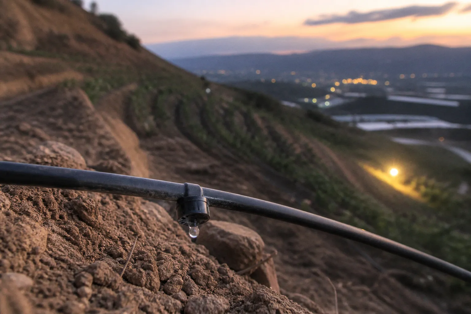
The exact difference depends on elevation, operating pressure, lateral length, friction loss and the emitter’s flow-pressure curve. The result should be measured in pressure, flow rate or distribution uniformity—not in kilograms per dunum.
For Lebanese growers working contour-planted olive blocks, cherry orchards on the Aarsal ridgeline or apple terraces in the Aakkar hills, the choice of emitter affects every later decision. If the lower rows receive too much water while the upper rows receive too little, the problem is not solved by adding more minutes to the irrigation schedule. More runtime usually deepens the imbalance.
The practical response is mechanical. Match the emitter to the elevation profile, protect it with filtration suited to the water source, and place the laterals so that gravity does less damage to pressure uniformity. Those three decisions will not make a poorly designed system perfect, but they determine whether the rest of the irrigation plan has a fair chance of working.
The Physics of Sloped Irrigation: Why Gravity Matters
Water pressure inside a polyethylene lateral is not a fixed number. It changes with elevation and with the friction created as water travels through the pipe. In a static column of water, a rise of roughly 10 metres corresponds to about 1 bar of pressure difference, or approximately 14.5 psi. The exact operating condition is more complicated because water is leaving through emitters along the line, but the principle remains simple: the lower end of a slope has more pressure available than the higher end.
That difference can be modest on a short block and substantial on a long lateral crossing uneven ground. A 30-metre elevation change between the lower valve area and the highest part of an orchard is not a minor detail in the hydraulic design. It represents a large static pressure difference before friction loss, pump behaviour, filters or regulators are considered.
Non-pressure-compensating emitters respond directly to this changing inlet pressure. Their flow path is usually based on a molded labyrinth or other fixed geometry. As pressure rises, discharge rises; as pressure falls, discharge falls. The relationship is not perfectly linear for every model, but the direction is predictable.
That means the emitter at the bottom of a slope may apply substantially more water than the emitter at the top during the same irrigation set. The lower tree can remain wet long after the upper tree has begun to experience water stress. In an orchard, this may appear as differences in soil moisture, canopy vigour, fruit size or the timing of drought symptoms. The visible symptoms are agricultural; the underlying problem is hydraulic.
Pressure-compensating, or PC, emitters address that variation with an internal flexible diaphragm. As inlet pressure rises, the diaphragm moves to restrict the flow path. As pressure falls, it relaxes and allows more flow. Within the manufacturer’s specified pressure range, the emitter can therefore maintain a much more stable discharge than a non-PC model.
The important qualification is “within the specified pressure range.” A PC emitter is not a pump, a pressure booster or a substitute for correct zoning. If pressure at the high end of the block falls below the emitter’s activation threshold, the diaphragm cannot maintain the rated flow. If pressure at the low end exceeds the emitter’s maximum operating pressure, compensation may no longer be reliable and component damage becomes possible.
On sloped land, uniformity starts with pressure management. The emitter can compensate for part of the elevation difference, but it cannot compensate for a system that never reaches its operating window.
The useful question is not whether the block is technically sloped. Almost every orchard has some variation. The useful questions are:
- How much elevation difference exists within one lateral?
- What pressure reaches the first and last emitter when the system is operating?
- How much flow variation is acceptable for the crop and soil?
- Is the water source clean enough to protect a diaphragm and a narrow flow path?
- Can the block be divided into practical pressure zones?
A field measurement is more useful than a visual estimate. Install pressure gauges at representative high and low points, or use temporary test points at the beginning and end of a lateral. Measure while the system is running, not only when the pipes are full but static. Then compare emitter discharge from different elevations using a graduated container and a fixed collection time. A few measurements will not replace a full hydraulic audit, but they can reveal whether the problem is elevation, clogging, inadequate pump pressure or excessive flow through the station.
Pressure-Compensating vs. Non-PC Emitters in Orchard Layouts
The choice between PC and non-PC emitters is a function of topography, lateral length, water quality and maintenance capacity. Price matters, especially when an orchard contains thousands of emission points, but the cheapest component is not always the cheapest system.
| Parameter | Non-PC emitter | PC emitter |
|---|---|---|
| Flow regulation | Fixed flow path; discharge changes with pressure | Diaphragm regulates discharge within a specified pressure range |
| Response to elevation | More flow at lower elevations and less at higher elevations | Better uniformity across moderate pressure differences |
| Best setting | Short laterals on relatively flat ground | Sloped, uneven or longer blocks with controlled pressure |
| Filtration requirement | Still needs filtration, but usually tolerates some variation in flow path design | Requires dependable filtration to protect the diaphragm and narrow passages |
| Behaviour below operating pressure | Flow falls with pressure | May fail to regulate and deliver below the activation threshold |
| Unit cost | Generally lower | Generally higher |
| Maintenance concern | Pressure variation is the main weakness | Clogging, diaphragm damage and unsuitable pressure are the main risks |
Non-PC emitters still have a legitimate place. A short lateral on a flat parcel, supplied at stable pressure, may achieve acceptable uniformity without the added cost of pressure compensation. They can also be a sensible choice for simple blocks where the operator can keep laterals short and inspect the system frequently.
They become a weaker choice when one lateral crosses a meaningful elevation difference or when the same station contains both low and high ground. A non-PC system may still operate, but the grower should know what is being traded away. The issue is not that every lower emitter will fail or that every upper emitter will be dry. The issue is that flow distribution becomes less predictable, and the difference can be large enough to affect irrigation scheduling.
PC emitters are not automatically the right answer for every slope either. They need adequate inlet pressure, a properly sized filtration system and pressure control that keeps the line inside the product’s working range. A blocked filter, undersized mainline or overloaded pump station can leave the upper part of a block below the minimum pressure required for compensation. In that situation, replacing the emitters without correcting the supply problem will produce an expensive version of the same fault.
Choosing the discharge rate
Common emitter ratings include 2, 4 and 8 litres per hour, although the available options vary by manufacturer and product line. The correct rating depends on soil infiltration, tree size, spacing, irrigation frequency, the number of emission points per tree and the capacity of the irrigation station.
For mature olives on terraced or contour-planted ground, 4 litres per hour is often a workable starting point when the system has been designed around that discharge. It is not a universal specification. Heavy soils may need a lower application rate or shorter irrigation pulses to limit ponding and runoff. Sandy soils may accept a higher total application rate but require more frequent irrigation because water moves beyond the active root zone more quickly.
A 2-litre-per-hour emitter can offer finer control for young trees, shallow soils or locations where runoff begins quickly. An 8-litre-per-hour emitter may be useful where the soil can absorb the application, where fewer emission points are needed, or where the system is designed to deliver a larger volume over a shorter period. But high discharge increases the total flow demand of the station. If the pump, filter or manifold is not sized for that demand, pressure drops and uniformity suffers.
Emitter discharge should therefore be considered together with the number of emitters per tree:
- A young tree with a small root zone may need fewer emission points and a lower total flow.
- A mature olive tree may need several points distributed around the wetted root zone rather than one concentrated outlet.
- On heavy soil, spreading the discharge across more points can reduce local ponding.
- On sandy or stony ground, the spacing and pulse length may matter more than the nominal emitter rate.
- Fertilizer injection should be based on the water actually reaching different parts of the block, not only on the volume leaving the pump.
Fertilizer distribution is where poor hydraulic uniformity becomes particularly costly. If the lower rows receive a higher flow, they may also receive a larger share of injected nutrients during part of the irrigation cycle. The upper rows then receive a weaker irrigation and fertigation treatment, even though both zones are controlled by the same valve.
Thresholds for Implementation: When to Upgrade Your System
There is no single elevation threshold that makes PC emitters mandatory for every farm. Soil, crop spacing, pressure, lateral diameter and emitter design all change the result. Still, several conditions should trigger a proper review rather than an assumption that the existing system is good enough.
1. Elevation difference within one lateral
Measure the vertical difference between the first and last emitter, not the total height of the farm. A block can have a large overall slope while individual laterals remain close to a contour. Conversely, a seemingly moderate parcel can contain a lateral that climbs sharply.
Once the pressure difference becomes a meaningful share of the emitter’s operating pressure, non-PC discharge variation can become difficult to manage with runtime adjustments. The operator may shorten irrigation to protect the lower rows, leaving the upper rows under-irrigated, or extend it to reach the upper rows and overwater the bottom.
2. Long laterals and friction loss
A long lateral loses pressure as water travels through it. The loss depends on pipe diameter, internal roughness, total flow, emitter spacing and the reduction in flow along the line. Elevation can either add to or offset that loss, depending on the direction of the run.
A 150-metre lateral crossing a 10-metre elevation change is not hydraulically equivalent to a 150-metre lateral on level ground. A non-PC emitter near the manifold may see a different pressure from one at the far end, and the elevation difference may either worsen or partly counter the friction loss. The only reliable way to understand the result is to calculate or measure it.
3. Mixed-elevation blocks under one valve
A saddle-shaped parcel, a series of terraces or a block with both a low pocket and a high ridge should not be treated as one uniform field. Pressure zoning is often more effective than asking one valve and one pump setting to serve every elevation.
A useful upgrade can combine several measures:
1. Divide the block into elevation bands that can be irrigated separately.
2. Install pressure regulators where they control the actual zone pressure, not merely the pressure at the pump.
3. Use PC emitters on laterals where elevation variation remains significant.
4. Add pressure gauges at high and low points so the system can be checked during operation.
5. Recalculate station flow if emitter discharge or spacing changes.
A staged conversion can make sense when only part of the orchard is affected. The steepest or longest sub-blocks can be converted first while short, nearly level corners continue to use non-PC emitters. The two types should not be mixed casually on one lateral. Mixing them can make field behaviour harder to interpret because each emitter type responds differently to the same pressure changes.
The economic case also needs to be made locally. PC emitters may reduce flow variation and make irrigation easier to manage, but the payback period depends on installation labour, replacement costs, water availability and price, energy use, crop value, and whether better uniformity actually improves marketable yield or reduces losses. In some orchards the upgrade may justify itself quickly through easier management and fewer dry spots. In others, the cost-effective first step may be pressure zoning, shorter laterals, better filtration or correcting an undersized mainline.
There is no sound basis for promising every grower a one-season return. Before replacing a full lateral set, compare the cost of the conversion with the measurable loss in uniformity and the practical value of correcting it. A small field trial on the most uneven sub-block can reveal more than a generic return-on-investment claim.
For mature olive blocks, scheduling the work during winter dormancy is usually less disruptive than attempting a major conversion at the beginning of the irrigation season. That is a planning advantage, not a reason to postpone a failing system indefinitely. If the upper rows are already under stress, the priority is to restore a workable pressure profile before the crop enters its most sensitive period.
Filtration Strategies for Lebanese Surface Water Sources
Emitter selection means little if the emitters are clogged. In Lebanese irrigation systems, clogging commonly comes from two broad sources: organic and mineral material in the water. The treatment must match the source rather than follow a standard filter specification.
Surface water from canals, rivers and irrigation networks can carry algae, organic fragments, suspended sediment and biofilm-forming material. The load varies with the intake, season, upstream activity and the condition of the conveyance network. A filter that performs well with relatively clear well water may load rapidly when connected to canal water.
A screen filter is useful for catching larger particles, but it is not always sufficient as the primary defence against organic surface-water loading. Algae and soft organic material can deform, pass through or accumulate against the screen. Once the material reaches a narrow emitter passage, it can restrict flow or create a distribution pattern in which some emitters continue to discharge while others slow down.
Two filtration approaches are commonly suited to heavier surface-water loads:
- Disc filtration. Grooved discs are compressed into a depth-filtration pack. The spaces between the discs capture suspended material through the depth of the element rather than relying only on a single flat surface. Disc units are practical where the organic load is moderate and regular flushing is possible.
- Sand media filtration. Water passes through a pressurised bed of graded media that captures suspended organic particles throughout the bed. Media filtration requires more space, backwash water and management, but it can be a stronger choice where algae and organic loading are persistent.
A secondary screen or disc stage can provide additional protection after the primary filter. The correct mesh or micron rating should follow the emitter manufacturer’s requirement and the actual water analysis. A finer filter is not automatically better if the system lacks the flow and backwash capacity to keep it clean. A loaded filter reduces pressure, and reduced pressure at the high end of a sloped orchard can be as damaging to uniformity as the original emitter choice.
Backflushing should be controlled by pressure differential and by observation of the source water, rather than by an arbitrary calendar alone. Heavy organic days may require more frequent cycles; a relatively clear period may require less. The operator should know the clean-filter pressure and the pressure at which a backflush is needed. If the filter is cleaned only after the upper rows show drought stress, the system is already operating outside its intended design.
Groundwater creates a different set of risks. Calcium carbonate can form scale in the labyrinth, while iron can create deposits or contribute to biological fouling after oxidation. Treatment depends on the water chemistry. A water analysis should establish pH, alkalinity, hardness, iron, manganese, suspended solids and other relevant parameters before an acid or oxidation programme is selected.
Acid injection cannot be prescribed responsibly as a fixed percentage followed by a guaranteed pH. The required dose depends on the acid used, its concentration, the source water’s alkalinity, the injection point, contact time and the target treatment. A measured pH response in one well does not predict the response in another. The system should be calibrated with a suitable meter, and the treatment should be managed according to the water analysis and the equipment manufacturer’s guidance.
The same caution applies to iron treatment. Aeration, oxidation, filtration or chlorination may be appropriate depending on the form and concentration of iron and on the rest of the water chemistry. A treatment that precipitates iron without a filter capable of removing the resulting particles simply moves the problem farther down the line.
Never treat chemical dosing as a replacement for filtration. Even a well-calibrated acid or chlorine programme cannot remove sand, algae fragments or sediment that the filter was supposed to capture. Chemical compatibility also matters: excessive dosing can damage seals, pipes or emitters, while inadequate flushing can leave treated material inside the system.
Surface water demands a filtration plan, not just a filter. The right unit must be sized for the organic load, the available backwash flow and the pressure the orchard still needs at its highest point.
Optimizing Lateral Line Placement on Uneven Terrain
Emitter selection addresses discharge variation. Lateral placement determines how much pressure variation the system creates before the water reaches the emitter.
On a sloped orchard, the conventional objective is to run laterals along the contour wherever the field layout permits. A contour follows approximately the same elevation, so the lateral does not continuously climb or descend. This reduces the hydrostatic pressure difference between its ends and makes the emitter’s job easier.
Contour planting and contour irrigation are not identical in every orchard. Existing terraces, access roads, rock outcrops and irregular boundaries may force compromises. Where a pure contour layout is impossible, divide the block into shorter sections and keep each lateral within a manageable elevation band. A shorter line that follows the local shape of the terrace is usually easier to control than a single line running directly up or down the entire slope.
Pressure zoning can support this approach. Each zone should have a defined elevation range, a known flow requirement and a regulator selected for the expected pressure. The regulator must not be treated as a magic device: it can control excessive inlet pressure, but it cannot create pressure that the pump and mainline do not supply.
Row spacing, emitter spacing and total flow
Lateral spacing should reflect the orchard’s planting pattern and the soil’s wetting behaviour. Mature olives planted at wider spacing may use one lateral per row, with emission points arranged to wet the active root zone rather than the trunk alone. Denser plantings may require a different arrangement, especially where roots from adjacent trees overlap.
Emitter spacing also affects station flow. If a lateral has too many outlets, total demand rises and pressure can fall below the PC emitter’s effective range. If spacing is too wide, the wetted pattern may remain discontinuous, particularly in coarse or stony soil.
The design should be checked as a set of connected values:
- row spacing and number of laterals;
- emitter spacing along each lateral;
- discharge per emitter;
- number of laterals operating at once;
- pipe diameter and allowable friction loss;
- pressure available at the highest outlet;
- filtration and regulator losses;
- pump flow at the required operating pressure.
Changing from 4 to 8 litres per hour, adding a second emitter at every tree or extending the lateral length can materially change the station flow. A system that worked with the original planting plan may become under-pressured after an expansion.
On long contour laterals, wider emitter spacing can sometimes keep total flow within the valve and pump capacity, but it should not be selected solely to reduce flow. The wetting pattern and root-zone coverage still matter. If the soil does not transmit water laterally, reducing the number of outlets may create dry bands even when the pressure gauges look acceptable.
Manifold orientation
Manifold routing is another tool, but it should be used with realistic expectations. Running a manifold along the slope can sometimes balance part of the elevation effect against friction losses among the lateral take-offs. Lower laterals may have more static pressure but greater friction loss in the manifold; upper laterals may have less static pressure and a shorter friction path.
This balancing effect depends on pipe diameter, manifold length, flow and the layout of the take-offs. It cannot replace pressure measurement or emitter compensation. On a block with a large elevation change, manifold orientation alone will not deliver uniformity if the laterals are too long, the pressure is inadequate or the emitters are unsuitable.
Where the terrain is especially irregular, a combination of shorter contour laterals, separate elevation zones and PC emitters is usually more dependable than trying to make one clever manifold arrangement solve every problem.
Checking the System Before the Season
Walk the block before the first irrigation set. Look for damaged laterals, exposed tubing, blocked outlets, missing emitters and sections where rodents, machinery or pruning work may have disturbed the line. The inspection should include the highest and lowest parts of every pressure zone.
Measure pressure while the system is operating. Static pressure alone can hide a shortage that appears as soon as the station begins drawing water. Check the pressure at the pump, after the filtration unit, at the manifold and at representative high and low laterals. The values should be compared with the emitter manufacturer’s operating range and with the design pressure of the zone.
A simple discharge test can reveal more than a visual inspection. Collect water from emitters at several locations for the same period, preferably from high, middle and low points. If the volumes differ substantially, identify whether the cause is pressure, clogging, damaged tubing or a mixture of emitter types. For a more formal evaluation, calculate a distribution-uniformity measure from multiple collection points rather than relying on one unusually good or bad emitter.
The filtration unit deserves its own inspection:
- confirm that the filter elements are intact and correctly installed;
- check the clean operating pressure;
- verify that the backflush cycle has enough flow and duration;
- inspect drain lines and valves for restrictions;
- clean the secondary screen;
- check whether sediment is accumulating in manifolds or dead-end sections;
- recalibrate pressure gauges if their readings appear inconsistent.
Chemical treatment should also be reviewed before the season. If acid or chlorine is used, confirm the injection equipment, non-return valve, storage safety and calibration procedure. Establish the target based on water analysis and system requirements. Do not assume that a concentration copied from another farm will produce the same pH or treatment effect in a different source water.
Finally, calculate the total simultaneous discharge of the station at the selected emitter rate. Compare that flow with the pump’s performance at operating pressure, not merely with the pump’s headline maximum flow. Allow room for filter loading, seasonal changes and pressure losses. A station that operates at the absolute edge of its capacity has little resilience when the water warms, the filter begins to load or another line is added.
The Practical Choice for Lebanese Farms
The most suitable drip irrigation emitter types for Lebanese farms are determined less by the crop name than by the relationship between terrain, pressure and water quality. An olive tree on a flat parcel does not need the same hydraulic treatment as an olive tree on a long, uneven terrace. A cherry orchard with clean well water presents a different problem from an orchard supplied by a sediment-heavy canal.
For relatively flat land with short laterals and stable pressure, non-PC emitters can remain a reasonable, economical option. For sloped land, long runs or blocks that combine several elevation bands, PC emitters provide a stronger margin of control—provided the system supplies their required pressure and protects them from clogging.
The upgrade decision should be based on measurements rather than on a guaranteed return. Record pressure at the high and low ends, compare emitter discharge, inspect the filtration system and estimate the cost of correcting the actual source of non-uniformity. Sometimes the best investment is a full PC conversion. Sometimes it is a shorter lateral, a new pressure zone, a larger mainline or a filtration upgrade.
What should not be ignored is the relationship between these parts. A PC emitter cannot fix an overloaded pump station. A new filter cannot correct a lateral that climbs the entire slope. A pressure regulator cannot compensate for an emitter that is below its activation range. And a carefully laid contour system will still perform poorly if the outlets are blocked.
The emitter on sloped land is not a commodity purchase. It is one part of a hydraulic system whose performance is decided by pressure, flow, filtration and layout together. Match the emitter to the elevation, match the filtration to the source water, and place the laterals with the contour wherever the orchard allows it. Everything else follows from those decisions.