Subsurface drip irrigation: a setup plan for olive orchards
Surface irrigation loses water in the least productive places: exposed soil, wheel tracks, field margins, and the air above the orchard.
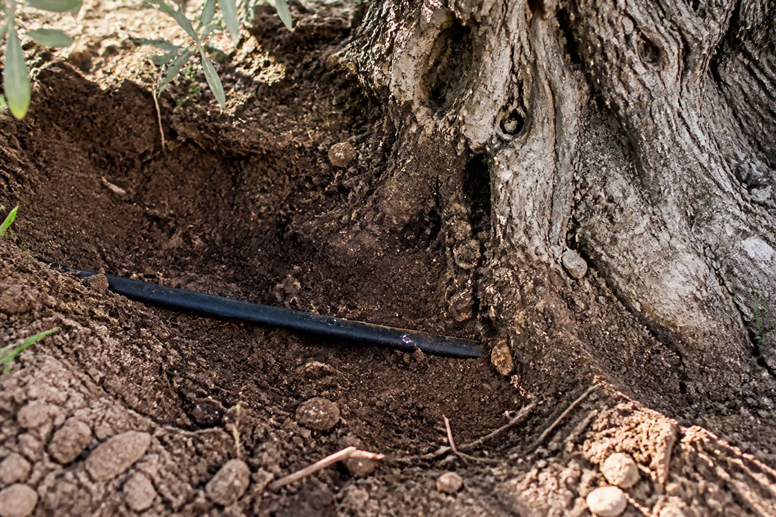
Subsurface drip irrigation installation moves the delivery point below the surface and places water closer to the active root zone, where application efficiency can be measured rather than assumed. In olive production, the potential reduction in water use is substantial—up to 30–60% compared with conventional surface methods—provided the buried system is designed around soil texture, root geometry, filtration, and shutdown protection.
The technology is not simply a matter of burying a hose between tree rows. A buried drip line is a permanent hydraulic asset. Its installation depth determines access to roots and resistance to cultivation; emitter spacing determines the shape of the wetted zone; pressure compensation determines distribution uniformity; and air-release hardware determines whether soil particles are pulled into the line every time the pump stops. A weak design conceals its failures underground until the orchard begins showing uneven canopy development or declining yield.
Optimizing burial depth and emitter placement for olive roots
The standard burial range for perennial subsurface drip irrigation systems is approximately 20–50 cm. That range is broad because olive orchards are not hydraulically uniform environments. Soil texture, compaction, tree age, root-zone depth, cultivation practices, and the position of the existing irrigation infrastructure all affect the correct installation level.
A shallow line, placed near the upper end of the root zone, can establish a wetted pattern quickly and may simplify early-season monitoring. It also has greater exposure to mechanical damage, surface temperature fluctuations, and disturbance from tillage or weed-control equipment. A deeper line is better protected from surface operations, but the system must overcome a greater soil volume before moisture reaches the most active roots. In compacted soils, that delay can become operationally significant.
For a super-intensive olive grove with trees spaced at approximately 3.5 × 1.5 m, a typical design uses one drip line per tree row. Emitters may be specified at 1.0–1.6 L/h with spacing of 50–75 cm. These figures are design references, not universal settings. The same emitter layout can perform differently in coarse sand and heavy clay because water does not spread through those profiles in the same way.
The buried drip line should run consistently along the row rather than drifting toward individual trunks. Olive roots expand over time, and a line placed directly against the trunk zone can create unnecessary mechanical and biological risk as the tree matures. The system should form a stable wetting corridor through the root zone, not a narrow wet spot beside each trunk.
Before excavation, establish four baseline measurements:
- The existing row spacing and tree spacing, including deviations in older or irregular blocks.
- The depth and density of the current active root zone, assessed through soil inspection rather than inferred from tree age alone.
- The soil texture and compaction profile at several points in the orchard.
- The current irrigation volume, operating pressure, irrigation duration, and distribution uniformity.
The baseline is essential because water savings are not calculated from the drip line specification. They are calculated from the difference between the previous application volume and the volume required to maintain the target soil-moisture profile under the new system.
A buried drip line is not an irrigation accessory. It is a permanent hydraulic network whose performance depends on the soil profile above and below it.
A practical installation sequence
A reliable subsurface irrigation design is easier to control when installation proceeds in defined phases rather than as one continuous field operation.
1. Map the orchard block. Divide the grove into hydraulic zones according to elevation, row length, soil type, and water-source capacity. Long rows and steep changes in elevation can produce pressure differences that are not visible from the pump house.
2. Inspect the soil profile. Use representative inspection points across the block. A single pit near the access road cannot describe a heterogeneous orchard, particularly where fill, rock, clay lenses, or compacted traffic lanes are present.
3. Select the burial depth. Place the line within the 20–50 cm range according to root distribution, soil behavior, and the machinery used for orchard maintenance. The depth should be recorded as an installation parameter, not left to operator judgment during trenching.
4. Set the lateral layout. In super-intensive plantings, one lateral per tree row is a common starting configuration. Wider-spaced or mature orchards may require a different arrangement if the wetted corridor does not reach enough of the active root zone.
5. Install filtration and air-management hardware first. The water source, filtration unit, pressure-control equipment, and air-release valves determine whether the buried network receives clean, stable water. Installing the laterals before resolving source-side hydraulics reverses the correct order of work.
6. Lay and bury the lines without sharp bends. Kinks and compression points reduce internal diameter and create localized pressure losses. The lateral should be installed at a consistent depth and protected at transitions, manifolds, and field edges.
7. Flush before closing the system. Open the lateral ends and remove construction debris, sediment, and installation contaminants before commissioning. A buried line that is closed with debris inside becomes difficult to recover.
8. Commission by zone. Measure inlet pressure, end-of-line pressure, flow, and operating time for each zone. Record these figures as the first operational baseline.
The installation cost is estimated at roughly $2,000–$3,000 per acre for a subsurface drip system, although the actual capital expenditure depends on field geometry, water-source upgrades, filtration, excavation conditions, control equipment, and labor. The figure should therefore be treated as an order-of-magnitude planning value, not a quotation for a Lebanese orchard.
Soil texture analysis: adjusting spacing for clay versus sandy groves
Emitter spacing is a soil-engineering decision. The objective is not to place the maximum number of emitters in the field. It is to create enough lateral and vertical moisture movement to support the olive root zone while limiting deep percolation, surface wetting, and unproductive evaporation.
Coarse sandy soils allow water to move downward quickly. If emitter spacing is too wide, the orchard develops a series of isolated vertical moisture columns rather than a continuous wetted corridor. The appropriate response is usually closer spacing and lower flow rates. The research range for emitter spacing can extend down to approximately 20 cm in sandy conditions, depending on the hydraulic behavior of the specific soil and the root-zone target.
Clay and silt soils produce a wider lateral wetting pattern. Water moves more slowly downward and can spread farther from the emitter, allowing wider spacing than in sand. This does not mean that clay automatically requires fewer emitters. Poorly structured clay, compacted layers, and low infiltration rates can cause ponding or delayed wetting even when the line is buried. The design must distinguish between a soil that spreads water laterally and a soil that simply resists infiltration.
A field texture assessment should examine more than the surface layer. For a buried system, the relevant profile includes the soil surrounding the line and the layers through which water must move to reach the root zone. A sandy surface over a compacted subsoil can behave very differently from a uniformly sandy profile. The same is true of silty topsoil over fractured clay.
| Design parameter | Coarse sandy soil | Clay or silt soil |
|---|---|---|
| Water movement | Predominantly downward and rapid | More lateral movement, slower infiltration |
| Emitter spacing | Closer, potentially down to about 20 cm in demanding conditions | Wider spacing may be feasible |
| Flow-rate logic | Lower flow can reduce deep percolation | Wider wetting can support higher spacing if infiltration is adequate |
| Main design risk | Water passing below the active root zone | Delayed infiltration, poor aeration, or localized saturation |
| Monitoring priority | Soil moisture at multiple depths | Lateral wetting and infiltration response |
For standard super-intensive orchard layouts, 50–75 cm emitter spacing and 1.0–1.6 L/h emitters provide a reference design range. The correct specification should be validated through wetting-pattern observation and pressure-flow measurements, not selected solely from a supplier catalogue.
Use the tree row as the production unit
The irrigation block should be organized around the tree row and its root-zone behavior. A common design mistake is to size the system from total acreage alone. Acreage determines the total line length and capital requirement, but it does not determine whether the final trees in a row receive the same hydraulic treatment as the first.
For each zone, calculate:
- Total lateral length.
- Number of emitters.
- Nominal flow per emitter.
- Total zone flow.
- Required inlet pressure.
- Expected pressure at the end of the longest lateral.
- Filtration capacity at peak operating flow.
The system should be evaluated at the least favorable point in the block, not only at the manifold. Pressure-compensating emitters help maintain more consistent discharge across pressure variation, but they do not compensate for undersized mains, blocked filters, inadequate pump capacity, or extreme elevation changes.
In Lebanon’s agricultural infrastructure context, this distinction is particularly relevant to cooperatives managing multiple small or fragmented holdings. A central pumping and filtration station can support several orchard blocks, but only if the hydraulic zones are separated according to actual field conditions. Treating every parcel as one uniform network creates a control problem that no sensor array can repair later.
Essential mechanical components for long-term system integrity
The visible portion of an irrigation system is usually the pump, tank, controller, or solar array. The buried portion determines whether the investment remains productive after installation. Subsurface lines require more disciplined mechanical protection because failures are concealed and access is expensive.
The core components are:
- Filtration at the water source. Sediment, organic matter, and mineral particles must be removed before they enter the laterals. Filtration capacity should match the maximum zone flow rather than the average daily demand.
- Pressure-compensating emitters. PC emitters stabilize discharge across a defined pressure range and reduce variation between the beginning and end of a lateral.
- Air-release and vacuum-relief valves. These protect the lines during filling and shutdown by managing trapped air and preventing negative pressure from drawing soil into the emitters.
- Flush valves at lateral ends. The ends of buried laterals need a controlled route for removing accumulated sediment and biological material.
- Pressure gauges and flow meters. Without these instruments, operators are forced to infer hydraulic performance from canopy appearance, which is a lagging and ambiguous indicator.
- Isolation valves for each zone. A zone must be shut down, flushed, inspected, or repaired without taking the entire orchard offline.
- Accessible manifolds and service points. Permanent infrastructure should be buried only where burial provides a clear protective benefit. Valves, filters, gauges, and flush assemblies need practical access.
The filter is not a passive component. Its pressure differential should be tracked during operation because a rising differential indicates loading and reduced hydraulic capacity. An irrigation system can continue to deliver water while its filter is progressively restricting flow; the resulting under-irrigation may first appear at the far end of the orchard.
A sensor layer can improve the system, but sensors should be installed to answer specific operational questions. Soil-moisture probes at more than one depth can indicate whether water is remaining in the active root zone or moving below it. Pressure sensors can identify zone instability. Flow meters can expose leaks, ruptures, and partial blockages. A dashboard without baseline thresholds is only a display.
Solar-powered pumping and the irrigation window
Solar-powered irrigation can reduce dependence on unstable grid supply or fuel-based pumping, but the photovoltaic array is not a substitute for hydraulic design. The pump must provide the required flow and pressure at the same time that the system is expected to operate. If the solar installation is sized only by daily energy production, it may fail to maintain pressure during the actual irrigation window.
The design sequence should therefore be:
1. Determine the required zone flow.
2. Determine the pressure needed at the filter, manifold, and highest or most distant lateral.
3. Calculate the pumping head, including elevation and friction losses.
4. Define the irrigation schedule and acceptable operating window.
5. Size the solar generation, inverter, pump, and any storage capacity around those hydraulic requirements.
For cooperative farms, shared pumping infrastructure may reduce duplicated capital expenditure, but it also introduces scheduling and governance constraints. Each member block needs a defined allocation, a measurable flow, and an operating record. Otherwise, the network becomes a shared asset with individually experienced shortages and no reliable mechanism for identifying the cause.
Preventing root intrusion and vacuum clogging in buried lines
Subsurface systems fail in two characteristic ways: the emitter becomes restricted from within, or the line draws soil particles inward during pressure collapse. Root intrusion is associated with the biological environment around the emitter and the quality of system management. Vacuum clogging is a hydraulic event that occurs when the line drains or contracts under negative pressure.
Anti-suction and pressure-compensating emitters are therefore not optional refinements in a permanent buried installation. When the pump stops, air must enter the system in a controlled manner. Without air-release and vacuum-relief protection, the line can generate suction that pulls fine soil into the emitter passages. A small amount of intrusion repeated across hundreds or thousands of emitters becomes a distribution problem rather than an isolated blockage.
The shutdown sequence matters. A zone should not be closed abruptly against a full line if the hydraulic design creates rapid pressure collapse. Air valves should be positioned at appropriate high points and near locations where air can accumulate. Flush valves should be placed at the downstream ends of laterals so that sediment has somewhere to leave the system.
Root intrusion should be managed as a design and operating issue, not treated with a single chemical response. The line should be positioned to avoid direct conflict with major trunk roots, and emitter technology should be selected for buried service. Irrigation schedules that create repeated shallow wetting near the surface can also influence root distribution, potentially increasing the biological pressure on a shallow line.
The system should be commissioned with a blockage-risk assessment:
- Is the source water carrying sand, algae, organic debris, or precipitated minerals?
- Does the filter remove the particle sizes relevant to the emitter passages?
- Can every lateral be flushed at a sufficient velocity?
- Are air valves accessible for inspection?
- Does the shutdown sequence prevent vacuum formation?
- Can a pressure or flow decline be detected before the trees show stress?
These questions convert buried-system integrity into measurable maintenance tasks. They also prevent the common error of equating installation completion with project completion.
The cheapest irrigation system is not the one with the lowest installation invoice. It is the one whose pressure, flow, and filtration data remain stable after burial.
Operational maintenance protocols for sustainable water savings
The claimed water saving of 30–60% is a performance range, not an automatic outcome. It depends on whether the orchard previously suffered from surface evaporation, runoff, excessive weed growth, or application outside the root zone, and whether the new system is operated according to actual soil and tree demand.
Maintenance should combine scheduled work with threshold-based intervention.
Daily or routine operating checks
During active irrigation periods, operators should record:
- Inlet pressure at the filtration station.
- Pressure at representative zone manifolds.
- Flow rate for each irrigation zone.
- Filter differential pressure.
- Pump operating time and energy consumption.
- Any visible discharge, wet patch, or unexpected vegetation above the buried line.
A flow decline at stable pressure can indicate blockage or a restriction downstream. A flow increase can indicate a rupture or open flush point. A pressure decline across the entire zone may originate at the pump, filter, or mainline rather than in the laterals.
Periodic line flushing
Flushing is a required operating function, not an emergency measure. Laterals should be flushed through their end valves according to water quality and observed sediment loading. The exact interval depends on the source and filtration performance; a fixed calendar schedule is less reliable than a protocol tied to pressure differential, flow change, and discharge quality.
Flush discharge should be directed away from tree trunks and protected soil surfaces where erosion or contamination could occur. The operator should record the condition of the discharge at the beginning and end of the operation. This provides a basic trend record for each zone.
Soil-moisture verification
Soil-moisture monitoring should confirm three conditions:
1. Water reaches the intended root-zone depth.
2. The wetted pattern extends laterally far enough to support the row.
3. Irrigation does not drive excessive water below the active root zone.
A single probe can produce a false sense of control. At minimum, measurements should represent different depths and, where soil variation is substantial, different positions across the orchard block. The objective is not to maximize soil moisture. It is to maintain a stable moisture profile with the least applied volume that preserves tree performance.
Seasonal adjustment
Olive water demand changes across the production cycle and with weather conditions. The irrigation controller should therefore be adjusted by season, crop stage, soil response, and available water—not left to a single annual runtime. A buried system can reduce evaporative losses while still over-irrigating if runtime is inherited from the previous surface method.
The correct adjustment process is incremental:
- Establish a starting runtime from the measured zone flow.
- Observe soil moisture at the target depths.
- Compare the response across soil types and orchard blocks.
- Adjust duration or frequency, but not both simultaneously unless the system is being reconfigured.
- Record the effect on flow, pressure, soil moisture, and tree condition.
This creates a usable baseline for future seasons. It also allows a cooperative to compare blocks using actual resource consumption rather than informal claims about which parcel is being irrigated adequately.
Converting installation into an investment decision
The capital expenditure for subsurface drip irrigation should be assessed against water availability, pumping energy, labor, crop value, and the cost of failure. Water saving alone is not enough to justify a system if filtration is neglected or if the orchard cannot maintain the required operating discipline.
A practical investment model should include:
- Buried laterals and installation labor.
- Pump, filtration, pressure regulation, and air-management hardware.
- Flow meters, gauges, valves, and access boxes.
- Power infrastructure, including solar generation where applicable.
- Replacement parts and annual maintenance.
- Expected reduction in pumping volume.
- Expected reduction in weed-control demand from drier surface soil.
- The value of improved distribution uniformity across the orchard.
- The cost of diagnosing and repairing buried failures.
The estimated setup range of $2,000–$3,000 per acre provides a starting capital envelope. The payback period cannot be responsibly calculated without local water pricing, energy costs, orchard size, operating hours, and current irrigation losses. A system installed in a water-constrained block may justify itself through avoided production risk even where direct energy savings are modest; a system installed in a low-cost, highly reliable water environment may have a slower financial return.
The engineering verdict is straightforward. Subsurface drip irrigation installation is justified when the orchard can support four conditions simultaneously: a correctly characterized soil profile, a hydraulically stable zone design, reliable filtration and air protection, and measured operational maintenance. Under those conditions, a buried system can reduce water use by up to 30–60% relative to surface methods while reducing surface evaporation and weed growth.
Without those conditions, burial merely hides the weaknesses. The line may still deliver water, but the orchard operator will no longer be able to see where the system is losing efficiency. That is not automation. It is deferred diagnosis.