Solar irrigation systems: 5 common installation mistakes
A solar irrigation system can fail without a dramatic breakdown. More often, the failure appears as a pump that starts late, loses pressure at midday, trips during hot weather, or delivers less water than the farm was designed to receive.
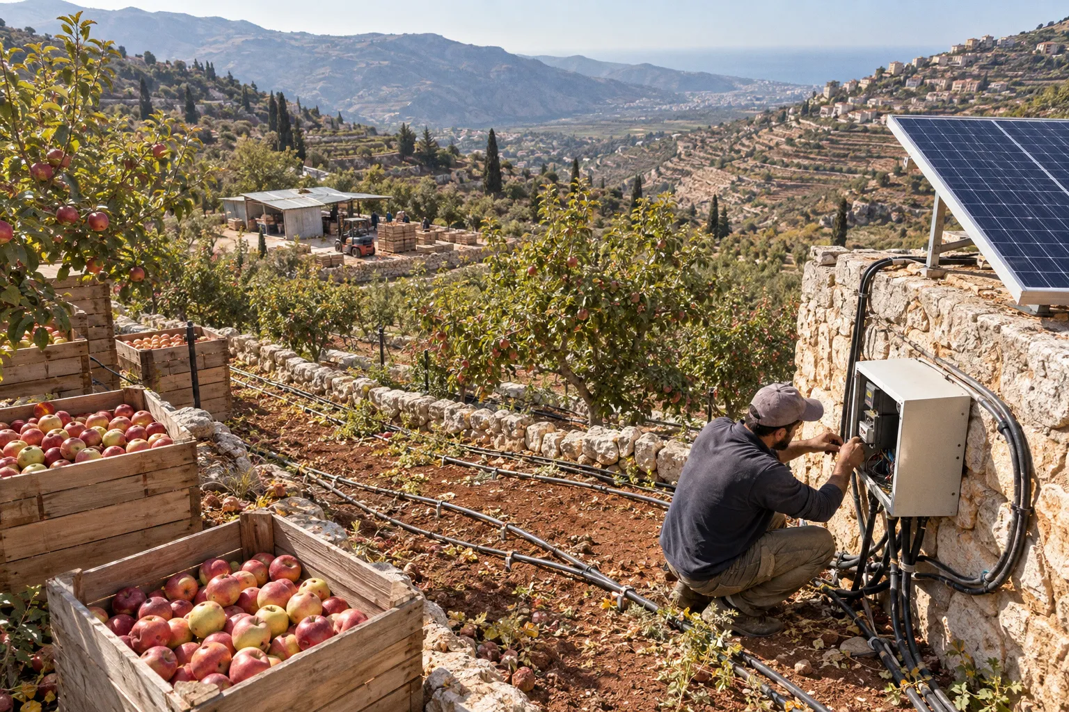
The panels may still look clean. The inverter may show no permanent fault. The borehole may still contain water. Yet the system underperforms because its components were specified as separate products rather than as one hydraulic, electrical, and agricultural system.
For Lebanese cooperatives and farms, the risk is particularly visible when a photovoltaic installation replaces diesel pumping. Solar generation follows the sun, while irrigation demand follows crop water requirements, reservoir levels, pumping depth, and the operating schedule of the field network. A design that ignores any one of those conditions can turn a promising infrastructure investment into a daily operating problem.
The five mistakes below are common solar powered irrigation system installation mistakes not because the underlying technology is mysterious, but because small errors at the design or installation stage are difficult to see once the equipment is commissioned. The symptoms usually appear later: in reduced flow, inverter derating, clogged filters, damaged electronics, or unexplained gaps in daily water delivery.
The Pitfalls of Mismatched Pump and PV Array Sizing
The first calculation is not the pump’s horsepower. It is the hydraulic duty the pump must perform.
That duty is defined by the total dynamic head: the vertical lift from the pumping water level to the delivery point, the pressure required by the irrigation network, and the friction losses in the pipes, fittings, valves, filters, and laterals. Static well depth alone is not enough. A borehole can have a comfortable water level when it is idle and a very different operating level after sustained pumping during the dry season.
A proper design therefore has to connect several measurements:
- the static water level and the expected pumping water level;
- the flow rate required by the irrigation zones;
- the pressure needed at filters, drip lines, or micro-sprinklers;
- the length, diameter, and material of the rising main and field pipework;
- the daily water volume required by the crops;
- the hours when useful solar power is available;
- the voltage and current range in which the pump controller can operate.
The crop calculation is just as important as the well calculation. A daily requirement based only on cultivated area can be misleading. Crop type, growth stage, weather, soil storage, irrigation efficiency, and the distribution uniformity of the field network all affect the actual volume that must be pumped. A system that looks adequate on an annual average may fail during the period when evapotranspiration and irrigation demand are highest.
Where sizing errors begin
The most common solar pump sizing errors in Lebanon occur when one component is selected first and the rest of the system is forced to accommodate it. A pump may be chosen from a catalogue because its rated head appears to match the borehole depth. An installer may then add a PV array that matches the motor’s nominal power without checking whether the array can hold the required operating voltage under hot, cloudy, or partially shaded conditions.
Typical failures include:
1. Selecting the pump from well depth alone. The relevant figure is the dynamic operating head at the required flow, not the total depth of the borehole.
2. Sizing the array for average daylight rather than the irrigation schedule. If the reservoir must be replenished during the strongest-demand period, the design must account for the hours when pumping is actually needed, including the effect of morning haze, afternoon heat, and passing cloud.
3. Ignoring the controller’s MPPT range. The array’s voltage may be high enough in cool, bright conditions but fall outside the controller’s useful operating window when module temperature rises or irradiance drops.
4. Treating pipe losses as a minor detail. Long field runs, narrow pipe, dirty filters, and excessive fittings can consume a meaningful part of the available head before water reaches the crop.
5. Using a safety margin without defining what it protects. Oversizing the pump does not automatically protect the farm. It may increase starting demand, reduce the time spent near the efficient operating point, and leave the PV array unable to provide stable power.
A pump that is too large for the array may repeatedly attempt to start and then fall back as the available power changes. A pump that is too small for the hydraulic demand may run continuously without delivering the volume needed to refill a storage tank or serve all irrigation zones. Both conditions can be mistaken for a weak solar resource.
| Design parameter | What should be established | What goes wrong when it is assumed |
|---|---|---|
| Water volume | Crop demand, irrigation method, area, and operating schedule | The system pumps enough for a test but not for the daily field requirement |
| Dynamic head | Pumping water level, delivery elevation, pressure, and pipe friction | The pump reaches the motor rating but not the required field pressure |
| PV array | Controller voltage window, current, temperature, and seasonal demand | The motor stalls or derates when conditions move away from the design point |
| Pump operating point | Flow and head at the expected range of solar input | The equipment runs outside its efficient range |
| Storage strategy | Tank size, refill timing, and priority zones | The farm depends on peak sun for water delivery instead of using storage to buffer variability |
The pump, controller, PV array, and irrigation network should be treated as one operating point. A catalogue rating for any single component cannot substitute for that system calculation.
A commissioning test should record more than whether water comes out of the pipe. Measure flow, discharge pressure, array voltage, array current, and pump behaviour at different points in the day. If possible, repeat the test when the reservoir is partly full and when several irrigation zones are open. These observations reveal whether the system is hydraulically constrained, electrically constrained, or simply being operated outside the schedule for which it was designed.
Thermal Management: Protecting Inverters from Overheating
A solar pump inverter can be electrically healthy and still reduce output because it is too hot. This is one of the common solar irrigation setup faults that operators often discover only after several weeks of summer operation.
Inverters and MPPT controllers generate heat while converting and regulating power. Their ability to dissipate that heat depends on ambient temperature, airflow, enclosure design, mounting surface, dust, and direct solar exposure. A unit installed on a wall that receives afternoon sun may operate in a much harsher environment than the same unit mounted under a ventilated canopy.
The problem is not limited to the air temperature shown by a nearby weather station. The enclosure, wall, cable glands, and internal heat sink can all become hotter than the surrounding air. Dust can reduce the effectiveness of cooling surfaces, while a sealed cabinet can trap heat even when it protects the electronics from rain.
Installation choices that preserve the thermal margin
A sound installation gives the inverter room to breathe and keeps it out of direct solar exposure. The manufacturer’s clearance requirements should take priority, but the following principles are broadly applicable:
- Mount the inverter on a stable, shaded surface with free air movement around the cooling surfaces.
- Do not place it inside a small sealed metal box unless the enclosure has been designed for heat dissipation.
- Keep the unit away from the exhaust path of another inverter, generator, pump controller, or battery system.
- Avoid mounting several units tightly together, especially when their hot air rises toward the intake of the unit above.
- Use a canopy or ventilated equipment shelter rather than relying on a thin sheet of metal that becomes a heat source in the afternoon.
- Keep dust, insects, and agricultural chemicals away from ventilation openings.
- Confirm that the enclosure rating suits the location, while also considering condensation and internal humidity.
An IP rating describes resistance to ingress under defined test conditions. It does not mean that a closed enclosure can remain cool in direct sun, nor does it remove the need to manage condensation. In humid coastal areas, greenhouse environments, and locations where the temperature changes sharply between day and night, trapped moisture can corrode terminals and circuit boards over time.
The operating symptoms are usually gradual. The pump may run normally in the morning, then lose speed or pressure as the inverter warms. It may recover later in the afternoon when the enclosure cools. Some systems display a thermal warning; others simply reduce output according to their protection logic. Restarting the unit repeatedly without addressing the heat source treats the symptom while preserving the fault.
A useful inspection compares operating conditions rather than relying on one isolated reading. Record the inverter’s displayed temperature, output, ambient conditions, and pump performance during the hottest part of the normal irrigation schedule. An infrared thermometer can help identify an unusually hot enclosure, loose terminal, or cable connection, but surface temperature alone does not replace the manufacturer’s operating limits or a qualified electrical inspection.
Thermal management also belongs in the maintenance plan. Ventilation openings should be checked for dust and insect nests. Cable glands should remain tight. Shade structures should not be removed during later civil works. A new wall, water tank, or sheet-metal roof can alter airflow and create a hot spot that was not present at commissioning.
Submersible Pump Placement and Borehole Sediment Risks
The pump’s position inside the borehole has two competing requirements. It must remain submerged during the lowest expected pumping water level, and it must stay far enough above the bottom to avoid drawing sediment into the hydraulic assembly.
Both errors are easy to make when the pump is installed according to the static water level or the total borehole depth rather than actual drawdown behaviour.
If the pump is set too close to the bottom, sand, silt, and mineral fines can enter the impeller and wear internal surfaces. The first sign may be a slow reduction in flow rather than a complete failure. Sediment can also increase the load on filters and clog drip emitters, creating a field-level problem that appears unrelated to the borehole pump.
If the pump is set too high, the water column may fall below the required submergence during sustained pumping. Submersible motors depend on the surrounding water for cooling. Loss of submergence can cause overheating, protective trips, or serious motor damage if the condition continues.
The correct setting depth should be based on the borehole’s behaviour under load. A step-drawdown or equivalent pumping assessment can show how the water level changes as the flow rate increases. The assessment should be interpreted alongside the well construction record, screen location, pump curve, and the installer’s knowledge of seasonal conditions.
A practical placement sequence is:
1. Establish the static water level and the expected dynamic level at the intended flow.
2. Identify the lowest water level that the pump may encounter during the dry operating season.
3. Maintain the manufacturer’s required submergence below that level.
4. Keep a defined sediment buffer above the bottom of the borehole and above any known accumulation zone.
5. Confirm that the setting depth is compatible with the pump, rising main, drop cable, splice, and borehead arrangement.
6. Mark and document the final depth so that later service work does not reposition the pump by guesswork.
The well floor should not automatically be treated as clean or stable. Older boreholes, poorly developed wells, and wells exposed to aggressive pumping can carry sediment even when the water looks clear at the surface. A change in turbidity, filter pressure, flow rate, or pump noise deserves investigation before the impeller and motor are damaged.
Pump placement is also linked to the irrigation network. If sediment reaches the field, a stronger filter may protect the emitters, but filtration adds pressure loss and requires cleaning. The better solution is to control sediment at the source through appropriate well development, pump positioning, intake protection where suitable, and a monitoring routine that catches deterioration early.
Electrical Safety: Surge Protection and Wiring Integrity
Photovoltaic irrigation systems combine long outdoor cable runs, exposed metal structures, power electronics, and a motor that may be located far from the array. That combination creates several pathways for damage: direct or nearby lightning effects, induced surges, poor earthing, damaged insulation, loose terminations, and DC arcing.
Surge protection is not a decorative addition to the control cabinet. The protection devices, conductors, bonding, and earthing arrangement must be designed as a coordinated system. A surge protective device that is badly selected, poorly bonded, or connected with long loops may provide much less protection than its label suggests.
The installation should address both the DC side between the array and controller and the AC or motor side where applicable. The appropriate device type and voltage rating depend on the system architecture, maximum PV open-circuit voltage, local exposure, and the manufacturer’s requirements. Protection should be installed where the cable enters the equipment and where the risk assessment indicates that a long external run needs additional control.
The main points are straightforward but often missed:
- Match the DC protection to the array’s maximum voltage under the expected temperature range.
- Provide suitable protection on the pump or AC side where the system architecture requires it.
- Bond module frames, mounting rails, metallic enclosures, and other accessible conductive parts according to the design.
- Use an earthing arrangement that is measured and documented rather than assumed from the presence of a ground rod.
- Route cables in UV-resistant protection and shield them from livestock, machinery, sharp edges, and standing water.
- Use glands and strain relief that maintain the enclosure’s environmental protection.
- Keep DC connectors compatible and properly assembled; mixed connector systems can create poor contact and heat.
- Inspect and retorque connections according to the equipment manufacturer’s procedure and applicable electrical practice.
- Keep polarity, cable identification, and isolation points clear for future maintenance.
The cost of protection cannot be judged only as a percentage of the purchase invoice. Its value depends on the exposure of the site, the length of the cable runs, the availability of replacement components, and the consequences of losing the irrigation system during the growing season. A failed controller can interrupt water delivery, damage a crop schedule, and require a difficult replacement even when the panels and pump remain usable.
Coastal installations need an additional layer of attention. Salt-laden air, humidity, and agricultural chemicals can accelerate corrosion at terminals and mounting points. Corrosion is not always visible at first: a connection may look intact while its contact resistance is increasing. Heat generated at that point can then worsen the connection, creating a cycle of oxidation and overheating.
Electrical safety should be verified before the pump is placed into routine operation. The test record should identify insulation checks, polarity, protective-device configuration, bonding continuity, earthing measurements, and the behaviour of the system under load. These are not paperwork exercises. They create a baseline that helps distinguish a new installation fault from a later maintenance problem.
Surge protection works as a chain. The device, its wiring, its bonding, and the earthing path must all be adequate; a strong component connected through a weak path is not a strong protection system.
The Hidden Impact of Shading on Solar Generation Efficiency
Shading is often treated as a visual nuisance: a tree branch, a water tank, a borehead, or a nearby wall that covers a small part of a panel for part of the day. Electrically, the effect can be more complicated.
PV modules contain cells and bypass diodes arranged in electrical sections. In a series-connected string, current is constrained by the weakest section in the operating path. Depending on the location and duration of the shadow, a bypass diode may activate and remove part of a module’s contribution. The result is not necessarily proportional to the visible area of the shadow.
That does not mean every small shadow will cut the string’s output in half. The outcome depends on module design, string topology, irradiance, the position of the shadow, the controller’s behaviour, and whether other modules are affected at the same time. A precise loss calculation requires a site measurement or a model based on the actual equipment. A generic example should not be presented as a field result.
How to assess a farm array
A useful shading assessment begins before the mounting structure is fixed:
1. Inspect the array location throughout the day, not only at the time of the initial site visit.
2. Map trees, buildings, tanks, poles, borehead structures, fencing, and likely future construction.
3. Pay attention to the low winter sun, when shadows are longer and may reach the array from objects that appear harmless in summer.
4. Mark the hours when direct irradiance is most valuable for the intended pumping schedule.
5. Compare the shadow pattern with the proposed string layout rather than treating the entire array as one undifferentiated surface.
6. Use module-level power electronics only when their cost, service requirements, and compatibility with the pump system are justified.
7. Recheck the site after construction, because a new shelter or elevated tank can create a new obstruction.
The important question is not whether an array receives some shade. It is whether the remaining unshaded production can meet the hydraulic duty during the hours available for pumping. If shade reduces the useful generation window, the system may need a different array layout, a larger storage tank, a revised pumping schedule, or a different string configuration.
Panel orientation and tilt belong to the same site-specific discussion. There is no universal tilt angle that maximises every irrigation system. The appropriate choice depends on latitude, roof or ground constraints, seasonal pumping demand, the orientation of the available area, cleaning access, wind exposure, and whether the design prioritises summer water delivery or a broader annual production profile.
For a farm that pumps mainly during the hot season, the design should model summer irradiance and summer water demand rather than rely on an annual production estimate. For a system intended to support winter irrigation as well, the lower sun angle and longer shadows become more important. The correct answer should come from local measurements or a project-specific model, not from applying a single angle to every Lebanese site.
Shading also changes over time. Trees grow, neighbouring structures appear, and dust accumulation can create a second form of partial obstruction. Maintenance records should therefore include the condition of the array surroundings, not only the cleanliness of the modules themselves.
Closing View
The five faults described here share a common cause: the installation is treated as a collection of equipment instead of an operating system. A pump curve does not explain the borehole. A panel rating does not explain the controller’s behaviour at high temperature. A surge protector does not replace bonding and proper wiring. A clean commissioning test does not prove that the array will deliver enough water during the most demanding part of the season.
The remedy is practical. Before procurement, calculate the hydraulic duty and match it to the controller and PV array. Before the hot season, inspect the inverter’s location, airflow, and operating temperature. Before setting the pump, understand drawdown and sediment conditions. Before energising the system, verify the protection and earthing chain. Before finalising the array layout, examine the site for daily and seasonal shade.
These steps do not guarantee that every installation will perform identically under changing weather or groundwater conditions. They do something more useful: they make the system’s limits visible. A cooperative can then decide whether to use storage, alter the irrigation schedule, change the array layout, improve filtration, or revise the pump selection before a small design mistake becomes a crop-season failure.
Solar irrigation is not simply diesel pumping with panels attached. It is a timed relationship between sunlight, electronics, water levels, hydraulic demand, and field operations. The installations that respect that relationship are easier to maintain because their problems can be measured, traced, and corrected.