Soil moisture sensors: choosing the right farm setup
For Lebanese farms, irrigation efficiency is rarely determined by the pump alone.
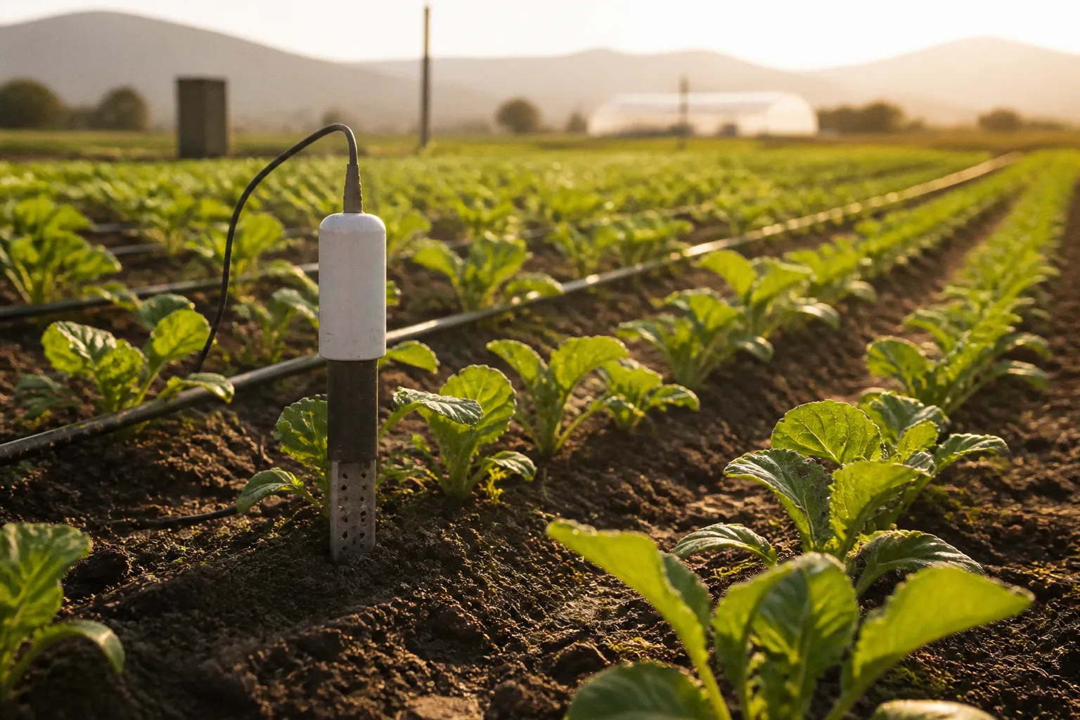
The larger variable is whether water is applied according to measured root-zone conditions or according to a fixed timer that ignores soil texture, crop development, salinity, temperature, and recent weather. Agriculture accounts for approximately 70% of global freshwater consumption, so even a modest reduction in unnecessary irrigation events has operational value when multiplied across cooperative fields.
The phrase soil moisture sensors for Lebanese farms covers several technically different instruments. A capacitance probe estimating volumetric water content is not equivalent to a tensiometer measuring root extraction effort. A sensor connected through cellular data does not create the same maintenance profile as one using LoRaWAN. A solar-powered field node may be preferable in a remote plot, but only if its energy budget and transmission range match the installation.
The correct setup is therefore not the sensor with the highest advertised accuracy. It is the smallest reliable measurement system that represents the crop root zone, survives the field environment, communicates consistently, and produces an irrigation decision better than the existing baseline.
The measurement problem: water volume is not water availability
Most irrigation mistakes begin with treating “soil moisture” as a single variable. It is not.
Volumetric water content, or VWC, describes the proportion of soil volume occupied by water. Capacitance and Frequency Domain Reflectometry sensors estimate VWC by measuring changes in the soil’s dielectric properties. These sensors respond quickly and are generally resistant to corrosion because the measurement can be performed without exposed conductive elements.
Soil matric potential describes a different condition: the force with which water is held by the soil. Tensiometers and granular matrix, or Watermark-type, sensors measure this suction force, commonly expressed in centibars, hectopascals, or kilopascals. The reading indicates how hard plant roots must work to extract water. It does not directly state the percentage of water in the soil.
That distinction matters because identical VWC readings can have different agronomic consequences in different soils. Sandy soil may hold less water overall but release it relatively easily until the root zone dries. Clay-rich soil can retain more water while making part of it difficult for roots to access. A single threshold copied from one field to another is therefore an uncalibrated assumption, not a management rule.
A useful deployment often combines two types of information:
- VWC measurement shows how much water is present in the measured soil volume.
- Matric potential measurement shows the extraction difficulty experienced by the root system.
- Temperature measurement supports interpretation of sensor drift and crop conditions.
- Electrical conductivity, or EC, measurement indicates salinity conditions and can help evaluate fertigation behavior.
- pH measurement can support nutrient-management decisions, although pH readings require careful calibration and should not be treated as a substitute for laboratory soil analysis.
Lebanese agrotech deployments such as SmartLand Agri in West Bekaa illustrate the direction of the market: in-ground sensors measuring moisture, temperature, pH, and EC are connected to mobile software for continuous irrigation and fertigation monitoring. The infrastructure is useful because it converts isolated readings into a time series. A single manual measurement is a snapshot. A sensor network can show infiltration, drying, irrigation response, and the effect of a fertigation cycle.
A sensor does not save water by existing in the field. It saves water only when its readings change the irrigation decision.
Sensor technologies compared
The practical comparison is between measurement principle, installation conditions, data requirements, and the decision the sensor can support. Accuracy in a product brochure is not enough. The relevant question is whether the instrument remains interpretable after installation in the target soil.
| Sensor type | Primary measurement | Main advantages | Main limitations | Suitable role |
|---|---|---|---|---|
| Capacitance | Volumetric water content, usually VWC | Fast response, corrosion-resistant operation, suitable for continuous monitoring | Sensitive to installation quality, soil salinity, calibration, and probe-soil contact | Automated irrigation scheduling and remote monitoring |
| FDR | Volumetric water content through dielectric response | Fast readings and robust continuous operation; operating frequencies above 100 MHz are common in this class | Requires calibration for soil conditions; interpretation can be affected by salinity and probe placement | Permanent sensor arrays in commercial fields |
| TDR | Moisture content and electrical conductivity | High measurement accuracy; performance is less dependent on soil density and temperature | Higher system cost and greater technical complexity than basic probes | Reference-grade monitoring, research, high-value production |
| Tensiometer | Soil matric potential or suction | Directly represents the effort required for roots to extract water | Requires correct installation and maintenance; can be unsuitable if allowed to dry beyond its operating range | Irrigation decisions based on plant water availability |
| Granular matrix / Watermark | Soil matric potential | Passive, practical for many field installations, can support threshold-based scheduling | Measures potential rather than water volume; response and interpretation depend on soil and installation | Lower-maintenance monitoring of root-zone stress |
| Manual soil moisture meter | Point reading, depending on instrument | Low initial cost and simple deployment | No continuous record, high operator dependence, limited spatial coverage | Spot checks and validation of automated networks |
FDR and capacitance sensors are often grouped in farm discussions because both rely on dielectric behavior, although implementation details vary. TDR has a stronger position where the operator needs high-accuracy moisture and EC information and can support the associated capital expenditure. Tensiometers and granular matrix sensors belong to a different measurement category and should not be selected merely because their display also reports a moisture-related number.
Capacitance and FDR: the default automation candidates
For many commercial farms, capacitance or FDR instruments provide the most practical foundation for irrigation automation. Their fast response allows the system to observe how quickly water moves through the profile after an irrigation event and how rapidly the root zone dries afterward.
The benefit is not limited to stopping irrigation when the top layer appears wet. A properly positioned array can distinguish between surface wetting and root-zone recharge. If the upper probe reacts immediately while a deeper probe remains dry, the system is showing incomplete infiltration. If the deeper probe rises sharply and remains saturated, the event may be exceeding the root zone’s storage capacity.
These sensors require calibration or at least field validation. Soil texture, bulk density, salinity, and air gaps around the probe influence the measurement. High salinity can alter dielectric behavior and create readings that are technically precise but agronomically misleading if the installation has not been adjusted for local conditions.
The phrase “soil moisture meters for agriculture” often refers to handheld instruments, but a handheld probe and a permanent capacitance array serve different operational purposes. The handheld device supports inspection. The fixed array supports scheduling, alarms, and historical analysis. A cooperative managing multiple plots will normally gain more from a smaller number of well-installed permanent stations than from a larger number of unstructured manual readings.
Tensiometers and granular matrix sensors: measuring plant effort
A tensiometer measures the suction force between soil and water. That makes it valuable when the management question is not simply whether water exists, but whether roots can extract it without increasing plant stress.
The instrument must be installed at representative root-zone depths and maintained according to its design. Its reading is meaningful only if the porous contact area is properly coupled to the surrounding soil. Poor contact creates an artificial delay or an unstable value. If the instrument dries beyond its functional range, the resulting data may not support an immediate irrigation decision.
Granular matrix sensors use a porous material whose electrical resistance changes with soil water potential. They are often considered when the farm needs a practical matric-potential signal with less routine servicing than a traditional water-filled tensiometer. They still require site-specific interpretation. A threshold that is suitable for one crop and soil texture cannot be transferred automatically to another.
The comparison between a tensiometer and a capacitive sensor is therefore not a contest between “old” and “new” technology. It is a choice between two measurement models:
- Choose VWC measurement when the operation needs a continuous picture of water storage and infiltration.
- Choose matric-potential measurement when the central question is root extraction difficulty.
- Combine both when the crop has a narrow stress tolerance, the soil profile is heterogeneous, or irrigation and fertigation decisions have material financial consequences.
TDR: when measurement quality justifies complexity
TDR sensors can measure both moisture content and soil electrical conductivity with high accuracy, while maintaining performance more independently of soil density and temperature than many simpler systems. That makes them attractive for high-value crops, experimental plots, and operations where salinity management is as important as irrigation volume.
The limitation is economic and operational rather than conceptual. TDR equipment can increase capital expenditure, integration requirements, and technical support needs. A high-end sensor installed in the wrong location, powered unreliably, or connected to an unread dashboard is a poor investment. The cost-benefit calculation must include the complete system: probe, enclosure, gateway, communication service, solar power equipment if required, installation labor, calibration, software, maintenance, and replacement risk.
For many cooperative farms, TDR is best deployed as a reference instrument rather than as the first sensor everywhere. It can be used to validate lower-cost stations or to monitor a field where salinity and soil heterogeneity make simpler measurements difficult to interpret.
Designing the sensor array around the root zone
The sensor count should follow field variability, not a vendor’s standard package. A farm with uniform soil, identical crop age, and a consistent irrigation layout needs a different array from a cooperative combining greenhouse blocks, open-field vegetables, orchards, and different elevations.
The first design decision is the management unit. A sensor station should represent an irrigation zone that can be controlled or adjusted independently. Installing one probe in a field supplied by several valves produces a clean data stream but a weak management signal. The measurement is not aligned with the decision.
For each zone, map the variables that can change water movement:
- soil texture and depth;
- slope and elevation;
- crop species and root depth;
- plant age and canopy development;
- irrigation method and emitter spacing;
- greenhouse or open-field exposure;
- drainage limitations;
- salinity patterns;
- distance from the pump or pressure-regulation point.
A practical root-zone installation often uses multiple depths rather than one probe near the surface. The exact depths depend on the crop and rooting pattern, which is why a universal installation specification would be misleading. The principle is more reliable: one measurement should represent the active upper root zone, while another should show whether irrigation is reaching the lower boundary or moving below it.
The profile response is more useful than a single number. After an irrigation event, the operator should be able to observe:
1. when water reaches the upper measurement point;
2. whether the wetting front reaches the deeper root-zone point;
3. how long the profile remains within the acceptable operating band;
4. whether the deeper layer remains saturated between events;
5. how quickly the crop removes water during the drying phase.
This is where soil moisture sensors for Lebanese farms become infrastructure rather than accessories. The station creates a baseline for a specific field, irrigation zone, and crop stage. The baseline should be revised when the crop canopy changes significantly, the irrigation layout is modified, or the sensor is moved.
Communication and power are part of measurement quality
A sensor that measures accurately but transmits intermittently is not a reliable irrigation instrument. Communication architecture must be selected before the number of probes is finalized.
LoRaWAN for distributed field networks
LoRaWAN can support low-power communication from multiple sensor nodes to a gateway. It is suited to installations where the field network covers a broad area and the sensor nodes need long battery or solar service intervals. The gateway then forwards data to the platform through an available backhaul connection.
Coverage cannot be assumed across all Lebanese agricultural regions, particularly in high-altitude or mountainous farms. The required validation is physical: install a test node at the intended location, measure signal stability across the operating period, and confirm that the gateway position is not blocked by terrain, structures, or vegetation.
LoRaWAN is efficient for small sensor messages. It is not a substitute for a general broadband connection, and it does not eliminate the need for gateway maintenance.
Cellular connectivity for independent plots
Cellular-connected stations can be simpler when plots are geographically separated and reliable mobile coverage is available. Each station can transmit directly to the cloud platform, reducing dependence on a local gateway.
The trade-off is a recurring communications cost and a greater dependence on network availability. The installation should log transmission failures separately from sensor faults. Otherwise, an operator may interpret missing data as stable soil conditions.
Wi-Fi for controlled environments
Wi-Fi is practical inside greenhouses, packing facilities, and compact farm blocks with stable power and network coverage. It is less suitable as the default for remote open-field stations. Range, power consumption, and dependence on local networking equipment become operational constraints.
Solar-powered stations
Solar power is appropriate for many remote installations, but the design must account for the complete energy budget:
- sensor sampling frequency;
- radio transmission frequency;
- gateway or modem consumption;
- battery capacity;
- panel orientation and shading;
- winter and low-light conditions;
- enclosure ventilation and water ingress;
- service access.
A panel sized only for average daytime operation will not guarantee continuous data. The station needs sufficient reserve for periods of reduced solar input. The practical objective is not maximum autonomy on paper; it is a predictable measurement record during the crop’s critical irrigation periods.
A phased implementation that controls capital expenditure
The safest deployment sequence is not “install sensors across every field and automate the valves.” That approach creates a large capital expenditure before the cooperative has established whether the data is representative or whether staff will use it.
A 36-month lifecycle calculation is more informative than the initial purchase price. The calculation should include equipment, installation, communication, calibration, maintenance, battery or power-system replacement, software fees, and the financial effect of missing data. The final category is often ignored. If the system produces gaps during irrigation windows, its nominal specification does not describe its operational value.
Phase one: establish the baseline
Before installing an automated network, record the existing irrigation schedule and the variables that can be measured without new infrastructure:
- irrigation duration by zone;
- pump operating time;
- approximate applied volume where flow measurement exists;
- crop and field area;
- current yield or harvest-quality indicators;
- visible runoff, ponding, or drainage;
- fertilizer injection timing;
- power interruptions and pump faults.
The baseline does not need to be perfect. It needs to be consistent enough to compare the sensor-supported regime against the timer-based regime.
Select representative zones rather than the easiest zones. Include at least one area with known variability, one standard production block, and one zone where irrigation costs or crop value justify closer monitoring. If every pilot station is placed in ideal soil near the pump, the results will not transfer to the rest of the cooperative.
Phase two: install and validate
Install the sensors with careful attention to soil contact, depth, orientation, and cable protection. The installation record should include coordinates, depth, soil description, crop stage, irrigation zone, sensor serial number, and calibration notes.
The first period is not an automation period. It is a validation period. Compare sensor outputs with field observations, manual readings where available, irrigation events, rainfall, and changes in soil conditions. Watch for values that remain constant during changing conditions, react too quickly for the soil profile, or diverge sharply from neighboring stations without an agronomic explanation.
The objective is to establish a usable baseline for each station. The baseline may be a VWC range, a matric-potential range, or a combined interpretation of both. It should be linked to crop response and irrigation performance rather than copied from a generic software template.
Phase three: connect data to irrigation decisions
Once the readings are stable, define the decision rules. These can begin as alerts rather than automatic valve commands. For example, the system may notify the operator when the upper root zone has dried beyond the established operating range while the deeper layer remains adequately supplied.
This staged approach exposes false triggers before they become irrigation events. It also gives staff time to understand the difference between a sensor fault and a genuine soil condition.
Automation should be introduced zone by zone. A controller can use sensor input to prevent unnecessary watering events compared with an unadjusted timer-based system, but the controller must also have safe operating limits. A communication failure should not create indefinite irrigation. A stuck valve should not be hidden by a dashboard that only displays sensor data.
Phase four: measure the result
The performance review should compare the sensor-supported period with the baseline using the same operational unit. Useful metrics include:
- irrigation events per zone;
- pump runtime;
- measured or estimated water volume;
- percentage of scheduled events overridden;
- duration of data gaps;
- number of high-moisture alarms;
- number of low-moisture alarms;
- yield and quality by crop block;
- fertilizer and EC trends where fertigation is monitored;
- maintenance hours per station.
Water reduction alone is not a sufficient success metric. A system that reduces irrigation but increases crop stress, salinity, or yield variability has transferred cost rather than removed it. Conversely, a system that maintains yield while reducing pump runtime may be economically valuable even if the field’s total water use is difficult to measure precisely.
The investment case is not “more sensors produce more data.” The investment case is that a defined sensor signal changes pump runtime, irrigation timing, or crop-loss exposure at a cost lower than the value created.
Cost-benefit logic without false precision
Exact prices for sensor brands delivered into Lebanon vary by supplier, import route, communications package, installation conditions, and exchange-rate exposure. A useful comparison should therefore avoid a fabricated market average and use a complete cost model instead.
For each deployment option, calculate:
Three-year system cost = hardware + installation + communication + software + power system + calibration + maintenance + replacement allowance
Then compare that figure with measurable operational value:
Three-year operational value = avoided pumping cost + avoided water cost where applicable + reduced crop-loss exposure + labor saved through automation − additional operating cost
The model should be calculated per irrigation zone, not only for the farm as a whole. A sensor network may be uneconomic in a low-value, uniform crop block but justified in a greenhouse, orchard, or saline zone where irrigation errors carry a higher cost.
A cooperative should also separate fixed and variable costs:
| Cost category | Fixed or variable behavior | Typical decision question |
|---|---|---|
| Sensor and gateway hardware | Mostly fixed at installation | Can the equipment survive the field environment for the planned lifecycle? |
| Installation labor | Fixed per station, but highly site-dependent | Are trenches, mounting points, and protective enclosures required? |
| Cellular or cloud service | Recurring | Is direct connectivity necessary, or can a local gateway reduce service cost? |
| Solar power equipment | Fixed with replacement exposure | Does the station need independent power, and what autonomy is required? |
| Calibration and field validation | Recurring or seasonal | Who will confirm that readings remain agronomically credible? |
| Maintenance and replacement | Irregular but unavoidable | Is access practical when a node fails during the production cycle? |
| Controller integration | Project cost | Can sensor data safely influence valves, or should it begin as an alert system? |
The payback period should not be calculated from a theoretical percentage of water savings. Use the cooperative’s recorded pump runtime, energy tariff, flow data, and production records. Where flow meters are absent, install them on the pilot zones if the budget allows. Without a credible baseline, the return-on-investment estimate will be dominated by assumptions.
Common failure modes in Lebanese deployments
The hardware is rarely the only source of failure. Most weak deployments fail at the boundary between field conditions, data interpretation, and management procedure.
One sensor for a heterogeneous field
A single probe cannot represent a field divided by soil texture, slope, crop age, and irrigation pressure. The dashboard may show a precise value, but precision at one point does not equal representativeness across the farm.
The response is to define management zones and place stations where their readings can support a specific control decision. A cooperative does not need a sensor in every square meter. It needs enough stations to capture the conditions that materially change irrigation management.
Using a surface probe to manage a deep root system
A shallow probe can show a wet surface after a short irrigation pulse while the active root zone remains dry. The opposite error is also possible: the surface dries quickly while deeper soil still supplies the crop.
Depth should follow root activity and irrigation movement. Multiple depths are preferable when the system needs to distinguish incomplete infiltration from excessive drainage.
Applying VWC thresholds without soil calibration
A percentage reading has no universal irrigation meaning. The same VWC value can describe different water availability in different soils. Sensor readings should be interpreted against field observations, soil texture, crop stage, and the plant’s response.
Treating salinity as a secondary issue
In irrigated production, salinity can affect both crop performance and sensor interpretation. TDR instruments can provide high-accuracy EC information, while other systems may require separate EC measurement. Fertigation monitoring should not rely on moisture data alone.
A field can appear sufficiently wet while the crop faces an unfavorable salt balance. The irrigation system then needs a management response that may involve water volume, drainage, fertilizer concentration, or timing rather than simply another sensor threshold.
Ignoring communications failures
Missing data is not neutral data. A platform should distinguish between a dry soil reading, a failed sensor, a dead battery, a lost gateway, and a cellular outage. The operator needs an explicit fallback rule for each condition.
Automating before validating
Directly connecting unvalidated sensor readings to valves creates avoidable risk. A probe installed with poor soil contact can trigger excessive irrigation or block a necessary event. Begin with monitoring, move to alerts, and only then permit closed-loop control in zones where the data history supports it.
Measuring equipment uptime but not farm outcomes
A network that reports every fifteen minutes is not necessarily improving production. The relevant question is whether the irrigation schedule became more accurate and whether the financial result improved. Sensor uptime is a technical metric. Yield stability, pump runtime, water use, and maintenance burden are system metrics.
Selecting the right configuration by farm type
Different Lebanese production environments justify different levels of instrumentation.
Open-field vegetables
Open-field vegetable production generally benefits from capacitance or FDR stations connected through LoRaWAN or cellular communication, depending on field geometry and coverage. The array should represent differences in soil texture, irrigation pressure, and planting stage.
For a cooperative managing several vegetable blocks, a shared dashboard is useful only if every station is tagged by crop, zone, and planting date. Otherwise, the data becomes an undifferentiated stream that cannot support scheduling.
Orchards
Orchards require attention to root depth, tree age, emitter placement, and spatial variability between rows. A probe placed too close to an emitter may report an artificially wet point; one placed too far away may represent dry soil that the tree is not using in the same way.
A two-depth installation can reveal whether irrigation is recharging the active root zone or moving below it. Matric-potential sensors can add useful information where the operator is managing water stress deliberately, but the interpretation must be linked to the crop and production objective.
Greenhouses and protected cultivation
Greenhouses offer better control over power and communications, making them suitable for more densely instrumented systems. Moisture, temperature, EC, and pH data can be combined with fertigation records. However, the enclosed environment can produce rapid changes in evaporation and substrate conditions, so the sampling interval and alert logic may need to be more responsive than in a broad open-field block.
Hydroponic systems should not be treated as soil-moisture applications. Their control variables are solution EC, pH, flow, temperature, dissolved oxygen where relevant, and reservoir behavior. A soil sensor is not the correct instrument for a soilless root environment.
Mountain and remote farms
Remote farms may require solar-powered nodes and a communication design validated on site. The power system should be sized for the sensor, radio, and gateway or modem, not for the probe alone. Maintenance access has a higher value in these locations, so enclosure quality, battery serviceability, and fault reporting should be included in the design.
The exact LoRaWAN coverage rate across all high-altitude farms in Mount Lebanon is not established in the available data. It should therefore be tested locally rather than assumed from a regional coverage map.
A decision framework for cooperatives
A cooperative should make the technology decision collectively but operate the measurements at zone level. The management structure needs three defined responsibilities:
1. Field responsibility: installation records, visual validation, and reporting of irrigation or crop anomalies.
2. Technical responsibility: power, communications, firmware, sensor health, calibration, and replacement.
3. Management responsibility: converting data into irrigation schedules, reviewing performance, and approving expansion.
Without these roles, the system becomes dependent on one technician or one supplier. That is a procurement risk, not a sensor specification.
The first procurement document should specify the data and service requirements rather than only naming sensor models. It should require:
- measurement type and units;
- expected sampling interval;
- calibration procedure;
- operating temperature and environmental protection;
- salinity limitations;
- communication protocol;
- power autonomy;
- data export capability;
- alarm states for missing data;
- warranty and replacement process;
- access to historical records;
- integration options for irrigation controllers.
A vendor that cannot explain how the system identifies sensor failure, communication loss, and abnormal readings has not supplied a complete agricultural monitoring solution. The probe is one component. The operating model is the system.
Final assessment
For most Lebanese farms beginning digital irrigation management, capacitance or FDR sensors offer the most balanced starting point: rapid response, compatibility with continuous monitoring, and a practical path toward irrigation scheduling. They should be installed at representative root-zone depths, calibrated against local soil conditions, and connected through a communication system proven at the site.
Tensiometers and granular matrix sensors remain valid where matric potential is the more useful decision variable. They are not substitutes for VWC measurement in every application, and they should not be described as measuring water volume directly. TDR belongs in deployments where high-accuracy moisture and EC data justify higher capital expenditure and technical complexity.
The correct three-year investment is the one that produces a defensible baseline, reduces unnecessary irrigation events, limits data gaps, and preserves yield and quality. A large sensor count without calibration or operational ownership has a negative return regardless of its technical specification. A smaller, well-designed network that changes pump runtime and irrigation timing can produce a measurable result.
The verdict is therefore specific: choose the measurement principle according to the crop decision, choose the array according to root-zone variability, choose communications according to terrain and power availability, and approve automation only after the readings have survived field validation. That sequence is less impressive than a full-farm technology launch. It is also more likely to produce an auditable return.